Pinpoint Test U: The Auxiliary Blower Motor Does Not Operate Correctly
Climate Control System
Pinpoint Test U: The Auxiliary Blower Motor Does Not Operate Correctly
Refer to Wiring Diagram Set 52, Auxiliary Climate Control for schematic and connector information Electrical Diagrams.
Refer to Wiring Diagram Set 54, Manual Climate Control System for schematic and connector information Electrical Diagrams.
Refer to Wiring Diagram Set 55, Automatic Climate Control System for schematic and connector information Electrical Diagrams.
Normal Operation
Under normal operation, ground for the auxiliary blower motor is provided through the auxiliary blower motor resistor. The auxiliary blower motor resistor is grounded. The auxiliary blower motor relay coils are supplied voltage. Auxiliary blower motor speed selection is received by the HVAC module from the rear auxiliary control. The auxiliary blower speed selector resistor is provided reference voltage and ground by the HVAC module. The auxiliary blower motor relay 1 coil receives ground if any blower speed but OFF is selected.
In LO, ground for the auxiliary blower motor is provided directly through the entire auxiliary blower motor resistor.
In MED-LO, auxiliary blower motor relay 2 is grounded by the HVAC module. The auxiliary blower motor ground is provided through one half of the auxiliary blower motor resistor. The second half of the auxiliary blower motor resistor is bypassed though auxiliary blower motor speed relay 2. The auxiliary blower resistor is grounded.
In MED-HI, auxiliary blower motor relay 3 is grounded by the HVAC module. The auxiliary blower motor ground is provided through one half of the auxiliary blower motor resistor. The second half of the auxiliary blower motor resistor is bypassed though blower motor speed relay 3. The auxiliary blower resistor is grounded.
In HI, auxiliary blower motor relays 2 and 3 are grounded by the HVAC module. The auxiliary blower motor ground is provided direct ground and not through any resistance inside the auxiliary blower motor resistor.
This pinpoint test is intended to diagnose the following:
- Wiring, terminals or connectors
- Auxiliary blower motor relay 1
- Auxiliary blower motor relay 3
- Auxiliary blower motor relay 2
- Auxiliary blower motor resistor
- HVAC module
PINPOINT TEST U : THE AUXILIARY BLOWER MOTOR DOES NOT OPERATE CORRECTLY
U1 CHECK THE AUXILIARY BLOWER MOTOR OPERATION
- Ignition ON.
- Turn the front auxiliary climate controls OFF.
Is the front auxiliary blower motor ON?
Yes
CARRY OUT the relay component test on the auxiliary blower motor relay 1. If OK, GO to U2.
No
GO to U4.
U2 CHECK CIRCUIT CHA05 (BN/WH) FOR A SHORT TO VOLTAGE
- Ignition OFF.
- Disconnect: Auxiliary Blower Motor C4106 (Expedition/Navigator) or C4334 (Expedition EL/Navigator L).
- Disconnect: Auxiliary Blower Motor Relay 1.
- Ignition ON.
- Measure the voltage between the auxiliary blower motor relay 1 socket pin 3, circuit CHA05 (BN/WH) and ground.
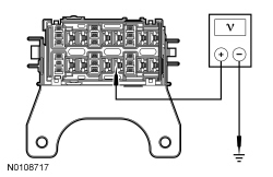
Is any voltage present?
Yes
REPAIR circuit CHA05 (BN/WH) for a short to voltage. TEST the system for normal operation.
No
GO to U3.
U3 CHECK CIRCUIT CH112 (VT/WH) FOR A SHORT TO GROUND
- Ignition OFF.
- Disconnect: HVAC Module- Dual Automatic Temperature Control (DATC) C228B or HVAC Module- Electronic Manual Temperature Control (EMTC) C2357B.
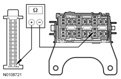
- Measure the resistance between ground and auxiliary blower motor relay 1 socket pin 1, circuit CH112 (VT/WH).
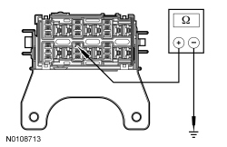
Is the resistance greater than 10,000 ohms?
Yes
GO to U14.
No
REPAIR circuit CH112 (VT/WH) for a short to ground. TEST the system for normal operation.
U4 CHECK THE AUXILIARY BLOWER MOTOR OPERATION
- Select all auxiliary blower speeds.
Is the auxiliary blower motor always 1 speed?
Yes
GO to U5.
No
GO to U6.
U5 CHECK CIRCUIT CHA06 (YE/VT) FOR A SHORT TO GROUND
- Ignition OFF.
- Disconnect: Auxiliary Blower Motor Relay 3.
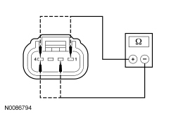
- Disconnect: Auxiliary Blower Motor Resistor C4343 (Expedition/Navigator) or C4107 (Expedition EL/Navigator L).
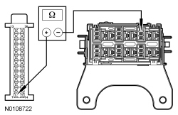
- Measure the resistance between auxiliary blower motor relay 3 socket pin 5, circuit CHA06 (YE/VT) and ground.
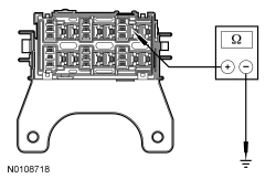
Is the resistance less than 5 ohms?
Yes
GO to U14.
No
REPAIR circuit CHA06 (YE/VT) for a short to ground. TEST the system for normal operation.
U6 CHECK THE AUXILIARY BLOWER MOTOR OPERATION
- Select all auxiliary blower speeds.
Is the auxiliary blower motor inoperative in any speed?
Yes
CARRY OUT the component test on the auxiliary blower motor resistor. Component Tests If OK, REPAIR circuit CHA06 (YE/VT) for an open. TEST the system for normal operation.
No
CARRY OUT the relay component test on the auxiliary blower motor relay 2 and 3. If OK, GO to U7.
U7 CHECK CIRCUIT CBP46 (WH/BU) FOR VOLTAGE
- Ignition OFF.
- Disconnect: Auxiliary Blower Motor Speed Relay 2 and 3.
- Ignition ON.
- Measure the voltage between the auxiliary blower motor relay 2 and 3 socket pin 2, circuit CBP46 (WH/BU) and ground.

Is the voltage greater than 10 volts?
Yes
GO to U8.
No
REPAIR circuit CBP46 (WH/BU) for an open. TEST the system for normal operation.
U8 CHECK CIRCUITS CH114 (GN/WH) AND CH113 (VT/GY) FOR A SHORT TO GROUND
- Ignition OFF.
- Disconnect: HVAC Module- DATC (Dual Automatic Temperature Control) C228B or HVAC Module- EMTC (Electronic Manual Temperature Control) C2357B.
- Measure the resistance between ground and:
- auxiliary blower motor relay 2 socket pin 1, circuit CH114 (GN/WH).
- auxiliary blower motor relay 3 socket pin 1, circuit CH113 (VT/GY).
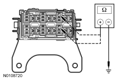
Are the resistances greater than 10,000 ohms?
Yes
GO to U9.
No
REPAIR circuit CH114 (GN/WH) or CH113 (VT/GY) for a short to ground. TEST the system for normal operation.
U9 CHECK CIRCUITS CH114 (GN/WH) AND CH113 (VT/GY) FOR AN OPEN
- Measure the resistance between HVAC module- DATC (Dual Automatic Temperature Control) C228B-14 or HVAC module- EMTC (Electronic Manual Temperature Control) C2357B-14, circuit CH114 (GN/WH), harness side and auxiliary blower motor relay 2 socket pin 1, circuit CH114 (GN/WH).
- Measure the resistance between HVAC module- DATC (Dual Automatic Temperature Control) C228B-1 or HVAC module- EMTC (Electronic Manual Temperature Control) C2357B-1, circuit CH113 (VT/GY), harness side and auxiliary blower motor relay 3 socket pin 1, circuit CH113 (VT/GY).
Are the resistances less than 5 ohms?
Yes
GO to U10.
No
REPAIR circuit CH114 (GN/WH) or CH113 (VT/GY) for an open. TEST the system for normal operation.
U10 CHECK CIRCUIT CHA08 (GN/OG) FOR AN OPEN
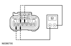
- Disconnect: Auxiliary Blower Motor Resistor C4343 (Expedition/Navigator) or C4107 (Expedition EL/Navigator L).
- For Expedition/Navigator only

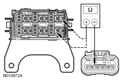
For Expedition/Navigator only, measure the resistance between auxiliary blower motor resistor C4343-1, circuit CHA08 (GN/OG), harness side and:
- auxiliary blower motor relay 3 socket pin 3, circuit CHA08 (GN/OG).
- auxiliary blower motor relay 2 socket pin 5, circuit CHA08 (GN/OG).
- For Expedition EL/Navigator L only
For Expedition EL/Navigator L only, measure the resistance between auxiliary blower motor resistor C4107-4, circuit CHA08 (GN/OG), harness side and:
- auxiliary blower motor relay 3 socket pin 3, circuit CHA08 (GN/OG).
- auxiliary blower motor relay 2 socket pin 5, circuit CHA08 (GN/OG).
Are the resistances less than 5 ohms?
Yes
GO to U11.
No
REPAIR circuit CHA08 (GN/OG) for an open. TEST the system for normal operation.
U11 CHECK CIRCUIT CHA08 (GN/OG) FOR A SHORT TO GROUND
- Measure the resistance between ground and:
- auxiliary blower motor relay 3 socket pin 3, circuit CHA08 (GN/OG).
- auxiliary blower motor relay 2 socket pin 5, circuit CHA08 (GN/OG).

Is the resistance greater than 10,000 ohms?
Yes
GO to U12.
No
REPAIR circuit CHA08 (GN/OG) for a short to ground. TEST the system for normal operation.
U12 CHECK CIRCUIT CHA07 (BU/GY) FOR AN OPEN
- For Expedition/Navigator only

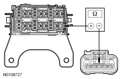
For Expedition/Navigator only, measure the resistance between auxiliary blower motor resistor C4343-3, circuit CHA07 (BU/GY), harness side and auxiliary blower motor relay 2 socket pin 3, circuit CHA07 (BU/GY).
- For Expedition EL/Navigator L only
For Expedition EL/Navigator L only, measure the resistance between auxiliary blower motor resistor C4107-3, circuit CHA07 (BU/GY), harness side and auxiliary blower motor relay 2 socket pin 3, circuit CHA07 (BU/GY).
Is the resistance less than 5 ohms?
Yes
GO to U13.
No
REPAIR circuit CHA07 (BU/GY) for an open. TEST the system for normal operation.
U13 CHECK CIRCUITS CHA08 (GN/OG), CHA07 (BU/GY) AND CHA06 (YE/VT) FOR A SHORT TOGETHER
- For Expedition/Navigator only
For Expedition/Navigator only, measure the resistance between auxiliary blower motor resistor:
- C4343-4, circuit CHA06 (YE/VT), harness side and auxiliary blower motor resistor C4343-1, circuit CHA08 (GN/OG), harness side.
- C4343-4, circuit CHA06 (YE/VT), harness side and auxiliary blower motor resistor C4343-3, circuit CHA07 (BU/GY), harness side.
- C4343-1, circuit CHA08 (GN/OG), harness side and auxiliary blower motor resistor C4343-3, circuit CHA07 (BU/GY), harness side.
- For Expedition EL/Navigator L only
For Expedition EL/Navigator L only, measure the resistance between auxiliary blower motor resistor:
- C4107-5, circuit CHA06 (YE/VT), harness side and auxiliary blower motor resistor C4107-4, circuit CHA08 (GN/OG), harness side.
- C4107-5, circuit CHA06 (YE/VT), harness side and auxiliary blower motor resistor C4107-3, circuit CHA07 (BU/GY), harness side.
- C4107-4, circuit CHA08 (GN/OG), harness side and auxiliary blower motor resistor C4107-3, circuit CHA07 (BU/GY), harness side.
Are the resistances greater than 10,000 ohms?
Yes
REPAIR circuit CHA06 (YE/VT) for an open between auxiliary blower motor relay 3 and the auxiliary blower motor resistor. TEST the system for normal operation.
No
REPAIR circuit CHA08 (GN/OG), CHA07 (BU/GY) or CHA06 (YE/VT) for a short together. TEST the system for normal operation.
U14 CHECK THE HVAC MODULE CONNECTION
- Inspect the HVAC module connectors for:
- corrosion.
- pushed-out terminals.
- damaged terminals.
- Connect and correctly seat all the HVAC module connectors.
- Clear the DTCs.
- Operate the system and verify the concern is still present.
Is the concern still present?
Yes
INSTALL a new HVAC module. TEST the system for normal operation.
No
The system is operating correctly at this time. The concern may have been caused by a loose or corroded connector. CLEAR the DTCs. REPEAT the self-test. TEST the system for normal operation.