B116B
Power Running Board (PRB)
Pinpoint Test D: DTCs B1167, B1168, B1175, B1178, B116B, B116D, B116C and B116E
Normal Operation
During Power Running Board (PRB) deployment, the PRB (Power Running Board) module supplies power to the PRB (Power Running Board) motor through circuit CPR41 (BU/WH) (LH) or CPR44 (BN/WH) (RH) and ground through circuit CPR42 (WH) (LH) or CPR45 (VT/GY) (RH). The PRB (Power Running Board) module stows the PRB (Power Running Board) by supplying power to the PRB (Power Running Board) motor through circuit CPR42 (WH) (LH) or CPR45 (VT/GY) (RH) and ground through circuit CPR41 (BU/WH) (LH) or CPR44 (BN/WH) (RH). The PRB (Power Running Board) module provides a regulated 10-volt power supply to the Hall-effect sensor (internal to the PRB (Power Running Board) motor) through circuit CPR47 (GY/BN). The Hall-effect ground is provided by the PRB (Power Running Board) module through circuit RPR47 (BU/GN). The PRB (Power Running Board) module monitors the PRB (Power Running Board) Hall-effect signal through circuit VPR43 (GY/BU) (LH) or VPR46 (GY) (RH). If the PRB (Power Running Board) module does not receive any signal from the Hall-effect sensor during operation, the PRB (Power Running Board) will stop.

This pinpoint test is intended to diagnose the following:
- Wiring, terminals or connectors
- LH or RH PRB (Power Running Board) motor assembly
- PRB (Power Running Board) module
PINPOINT TEST D : DTCs B1167, B1168, B1175, B1178, B116B, B116D, B116C and B116E
D1 CHECK FOR A SHORT TO VOLTAGE IN THE HALL-EFFECT SENSOR SIGNAL, DEPLOY OR STOW CIRCUIT
- Ignition OFF.
- Disconnect: PRB (Power Running Board) Module C3313A.
- Disconnect: PRB (Power Running Board) Module C3313B.
- Ignition ON.
- For DTC B1167, B1168, B116B or B116D, measure the voltage between LH PRB (Power Running Board) motor C3185-5, circuit VPR43 (GY), harness side and ground; and between LH PRB (Power Running Board) motor C3185-3, circuit CPR41 (BU/WH), harness side and ground; and between C3185-1, circuit CPR42 (WH), harness side and ground.

- For DTC B1175, B1178, B116C or B116E, measure the voltage between RH PRB (Power Running Board) motor C3186-5, circuit VPR46 (GY/OG), harness side and ground; and between RH PRB (Power Running Board) motor C3186-3, circuit CPR44 (BN/WH), harness side and ground; and between C3186-1, circuit CPR45 (VT/GY), harness side and ground.
Is any voltage present?
Yes
REPAIR the circuit. CLEAR the DTCs. REPEAT the self-test.
No
GO to D2.
D2 CHECK FOR A SHORT TO GROUND IN THE HALL-EFFECT SENSOR SIGNAL, DEPLOY OR STOW CIRCUIT
- Ignition OFF.
- For DTC B1167, B1168, B116B or B116D, measure the resistance between LH PRB (Power Running Board) motor C3185-5, circuit VPR43 (GY/BU), harness side and ground; and between LH PRB (Power Running Board) motor C3185-3, circuit CPR41 (BU/WH), harness side and ground; and between C3185-1, circuit CPR42 (WH), harness side and ground.
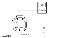
- For DTC B1175, B1178, B116C or B116E, measure the resistance between RH PRB (Power Running Board) motor C3186-5, circuit VPR46 (GY), harness side and ground; and between RH PRB (Power Running Board) motor C3186-3, circuit CPR44 (BN/WH), harness side and ground; and between C3186-1, circuit CPR45 (VT/GY), harness side and ground.
Is the resistance greater than 10,000 ohms?
Yes
GO to D3.
No
REPAIR the circuit. CLEAR the DTCs. REPEAT the self-test.
D3 CHECK FOR AN OPEN IN THE HALL-EFFECT SENSOR SIGNAL, DEPLOY OR STOW CIRCUIT
- Ignition OFF.
- For DTC B1167, B1168, B116B or B116D, measure the resistances between PRB (Power Running Board) module C4322A or C4322B, harness side and LH PRB (Power Running Board) motor C3185, harness side using the following chart:
LH Motor Connector Circuit PRB (Power Running Board) Module Connector C3185-5 VPR43 (GY/BU) C3313B-9 C3185-3 CPR41 (BU/WH) C3313A-1 C3185-1 CPR42 (WH) C3313A-2

- For DTC B1175, B1178, B116C or B116E, measure the resistances between PRB (Power Running Board) module C4322A or C4322B, harness side and RH PRB (Power Running Board) motor C3186, harness side using the following chart:
RH Motor Connector Circuit PRB (Power Running Board) Module Connector C3186-5 VPR46 (GY) C3313B-10 C3186-3 CPR44 (BN/WH) C3313A-4 C3186-1 CPR45 (VT/GY) C3313A-3

Is the resistance less than 5 ohms?
Yes
GO to D4.
No
REPAIR the circuit(s). CLEAR the DTCs. REPEAT the self-test.
D4 CHECK FOR A SHORT BETWEEN THE STOW AND DEPLOY CIRCUITS
- For DTC B1167, B1168, B116B or B116D, measure the resistance between LH PRB (Power Running Board) motor C3185-3, circuit CPR41 (BU/WH), harness side and C3185-1, circuit CPR42 (WH), harness side.
- For DTC B1175, B1178, B116C or B116E, measure the resistance between RH PRB (Power Running Board) motor C3186-3, circuit CPR44 (BN/WH), harness side and C3186-1, circuit CPR45 (VT/GY), harness side.
Is the resistance greater than 10,000 ohms?
Yes
GO to D5.
No
REPAIR the circuit. CLEAR the DTCs. REPEAT the self-test.
D5 CHECK THE PRB (Power Running Board) MOTOR FOR AN OPEN CIRCUIT
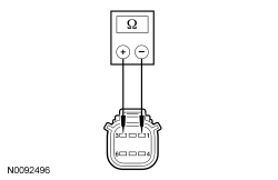
- For DTC B1167, B1168, B116B or B116D, measure the resistance between LH PRB (Power Running Board) motor C3185-3, circuit CPR41 (BU/WH), component side and C3185-1, circuit CPR42 (WH), component side.

- For DTC B1175, B1178, B116C or B116E, measure the resistance between RH PRB (Power Running Board) motor C3186-3, circuit CPR44 (BN/WH), component side and C3186-1, circuit CPR45 (VT/GY), component side.
Is any measurable continuity present?
Yes
GO to D6.
No
INSTALL a new PRB (Power Running Board) motor. REFER to Power Running Board (PRB) Motor . CLEAR the DTCs. REPEAT the self-test.
D6 CHECK THE PRB (Power Running Board) MOTOR FOR A SHORT TO GROUND
- For DTC B1167, B1168, B116B or B116D, measure the resistance between LH PRB (Power Running Board) motor C3185-1, circuit CPR 42 (WH), component side and ground.

- For DTC B1175, B1178, B116C or B116E, measure the resistance between RH motor C3186-1, circuit CPR45 (VT/GY), component side and ground.
Is the resistance greater than 10,000 ohms?
Yes
GO to D7.
No
INSTALL a new PRB (Power Running Board) motor. REFER to Power Running Board (PRB) Motor . CLEAR the DTCs. REPEAT the self-test.
D7 CHECK THE PRB (Power Running Board) MODULE FOR CORRECT OPERATION
- Connect: PRB (Power Running Board) LH Motor C3185.
- Connect: PRB (Power Running Board) RH Motor C3186.
- Visually inspect all PRB (Power Running Board) module connectors.
- Check for:
- corrosion.
- pushed-out pins.
- Connect all PRB (Power Running Board) module connectors and make sure they seat correctly.
- Operate the system and verify the concern is still present.
Is the concern still present?
Yes
INSTALL a new PRB (Power Running Board) module. REFER to Power Running Board (PRB) Module . CLEAR the DTCs. REPEAT the self-test.
No
The system is operating correctly at this time. Concern may have been caused by a loose or corroded connector. CLEAR the DTCs. REPEAT the self-test.