Computers and Control Systems: Description and Operation
System Operation:
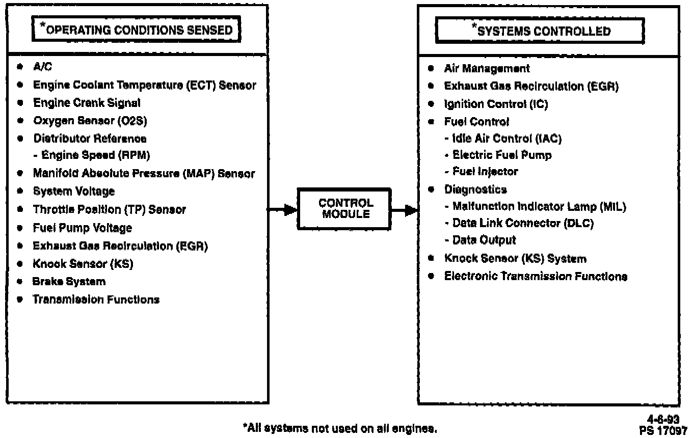
Control Module - Block Diagram:

SYSTEM DESCRIPTION
The Engine Control Module (ECM) and the Powertrain Control Module (PCM) will both be commonly referred to as a control module. The control module is designed to maintain exhaust emission levels to Federal or California standards, while providing good driveability and fuel efficiency. The control module monitors numerous engine and vehicle functions and controls the following operations:
- Fuel Control
- Ignition Control (IC)
- Knock Sensor System (KS)
- Secondary Air Injection (AIR) System
- Exhaust Gas Recirculation (EGR)
- Automatic transmision shift functions (PCM Only)
The control module supplies a buffered 5 or 12 volts of power to various sensors or switches. This is done through resistance in the control module which is so high in value that a test light will not light when connected to the circuit. In some cases, even an ordinary shop voltmeter will not give an accurate reading because its internal resistance is too low. Therefore, the use of a 10 megohm input impedance digital voltmeter J 39200 or equivalent is necessary to assure accurate voltage readings.
The input/output devices in the control module include analog to digital converters, signal buffers, counters and special drivers. The control module controls output circuits such as the injectors, EGR, A/C clutch relay, etc. by controlling the ground circuit through transistors or a device called a Quad-Driver Module (QDM) in the control module.
The control module has a built-in diagnostic system that recognizes and identifies possible operational problems. The control module signals the driver through a Malfunction Indicator Lamp (MIL) (Service Engine Soon light) located on the instrument panel. The MIL light will remain "ON" until the problem is identified and repaired. This same light is combined with the built-in diagnostic system in order to assist the technician in locating and correcting problems within the system. It does this by flashing a series of codes which identify the possible problem areas at fault. The control module also allows for near normal driving conditions during system malfunction, through the use of the built-in backup system. The backup system remains in effect until repairs can be made.