Front Steering Knuckle: Service and Repair
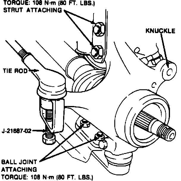
Fig. 13 Steering Knuckle Removal:
REMOVAL
1. Raise and support front of vehicle.
2. Remove wheel and tire assembly.
3. Remove brake hose retaining clip from strut, then disconnect hose from caliper.
4. Unfasten caliper from steering knuckle and support caliper.
5. Remove rotor, then the hub as mentioned previously.
6. Remove splash shield.
7. Remove tie rod using tool No. J-21687-02 or equivalent.
8. Remove two ball joint to control arm and tension rod attaching nuts and bolts.
9. Remove steering knuckle to strut attaching nuts and bolts and the steering knuckle, Fig. 13.
Fig. 14 Hub Bearing Removal:
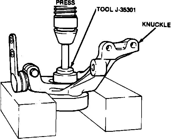
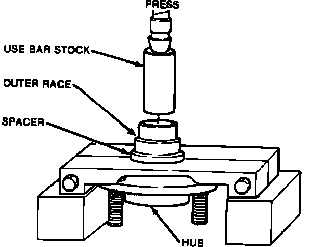
Fig. 15 Outer Bearing Race Removal:
DISASSEMBLY
1. Remove inner seal, snap rings and inner bearing race from steering knuckle.
2. Press hub bearing from knuckle, Fig. 14.
3. Press outer bearing race from hub, Fig. 15. The hub bearing, both inner and outer seals and races must not be reused.
ASSEMBLY
1. Install outer snap ring to knuckle.
2. Install hub bearing assembly using a suitable press.
3. Install inner snap ring, then the inner and outer seals using tool J-35303 or equivalent.
4. Install outer race using tool No. J-3502 or equivalent.
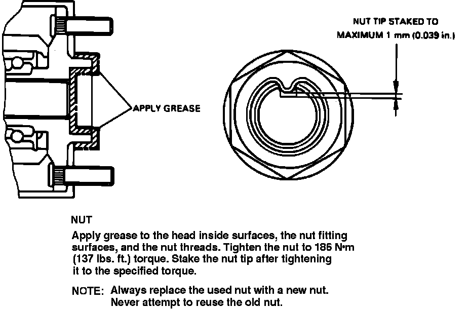
Fig. 12 Hub Spindle Nut Installation:
NOTE: For torque specifications refer to Steering and Suspension/Steering/Specifications/Mechanical.
INSTALLATION
1. Install ball joint to control arm attaching nuts and bolts and torque to specification.
2. Install strut to knuckle attaching nuts and bolts and torque to specification.
3. Install tie rod to knuckle attaching nut and torque to specification.
4. Install brake rotor.
5. Install brake caliper to knuckle attaching bolts and torque to specification.
6. Install brake hose to caliper and torque fitting to specification.
7. Install wheel and tire assembly, then lower vehicle.
8. Apply suitable grease to axle shaft threads and nut. After tightening nut to specified torque, stake nut, Fig. 12.
9. Tighten wheel nuts, then bleed brake system.