Troubleshooting
Fig. 63 Vacuum & voltage chart.:
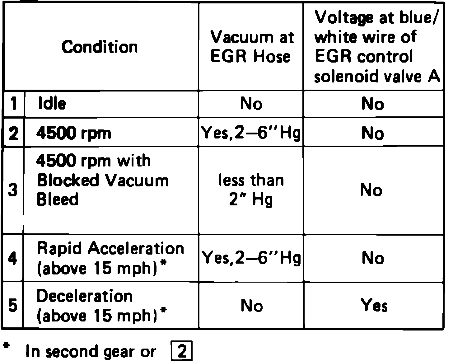
VOLTAGE IS AVAILABLE FOR CONDITIONS 1, 2 OR 3
1. Check thermosensor for continuity.
2. If there is continuity, replace thermosensor and repeat test.
3. If there is no continuity, disconnect hose from control switch and connect vacuum gauge to hose.
4. If there is no vacuum at idle, replace control switch and repeat test.
5. If there is no vacuum at idle, check for voltage at control switch solenoid valve.
6. If there is no voltage to valve with ignition switch on, replace control switch solenoid valve and repeat test.
7. If there is voltage, replace speed sensor and repeat test.
NO VOLTAGE IS AVAILABLE BUT VACUUM IS AVAILABLE FOR CONDITION 1 OR VACUUM IS GREATER THAN 2 IN. HG. FOR CONDITION 3
1. Replace EGR control valves A and B.
2. Check vacuum hose routing and correct as necessary.
VOLTAGE IS AVAILABLE FOR CONDITION 4
1. Replace control switch.
NO VOLTAGE IS AVAILABLE FOR CONDITION 5
1. Run engine at idle, by-pass speed sensor, disconnect vacuum line at control switch and check for vacuum.
2. If there is vacuum, reconnect vacuum line and check for voltage at EGR control solenoid valve A.
3. If there is no voltage, replace control switch and repeat test.
NO VACUUM OR VOLTAGE AVAILABLE FOR CONDITIONS 2 & 4
1. Run engine at 4500 RPM and check for ported vacuum at inlet of EGR control solenoid valve A.
2. If there is no vacuum, check vacuum hose routing and carburetor port. Correct as necessary and repeat test.
3. If there is vacuum, replace EGR control solenoid valve A.
VACUUM & VOLTAGE ARE AVAILABLE FOR CONDITION 5
1. Replace EGR solenoid valve A.