Transmission Removal
Transmission RemovalSpecial Tools Required
^ Engine support hanger, A and Reds AAR-T-12566
^ Engine hanger adapter VSB02CO00022
^ Engine hanger balancer bar VSB02CO00019 Front subframe adapter VSB02CO00016 These special tools are available through the Honda Tool and Equipment, Program 1-888-424-6857.
NOTE:
^ Use fender covers to avoid damaging painted surfaces.
^ Special tool Reds engine support hanger AAR-T-12566 must be used with the side engine mount installed.
1. Make sure you have the anti-theft codes for the radio and navigation system, then Write down the customer's audio presets.
2. Lift the vehicle up on a lift, and make sure it is securely supported.
3. Remove the front inner fender and splash shield.
4. Remove the drain plug (A), and drain the automatic transmission fluid (ATF).
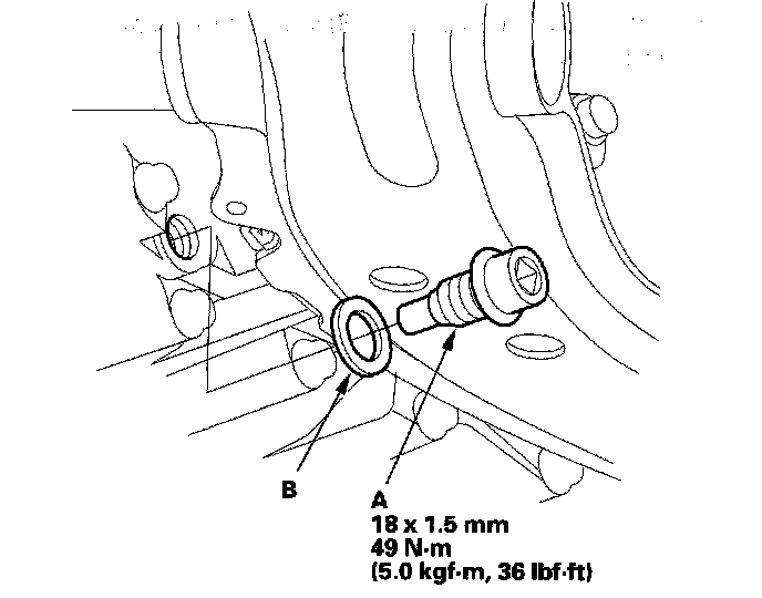
5. Reinstall the drain plug with a new sealing washer (B).
6. Disconnect the negative cable from the battery first, then disconnect the positive cable.
7. Remove the battery hold-down bracket, battery, and battery tray.
8. Remove the intake air duct and air cleaner housing.
9. Loosen the two bolts securing the rear of the battery base, and remove the two bolts securing the front of the battery base, then remove the battery base.
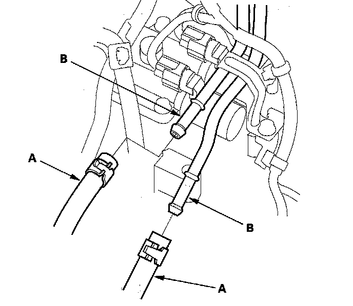
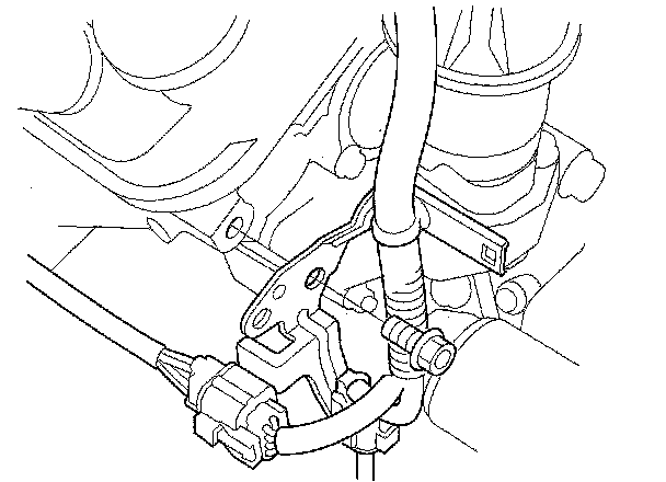
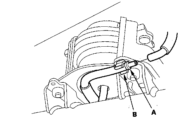
10. Disconnect the ATF cooler hoses (A) from the ATF cooler lines (B). Turn the ends of the ATF cooler hoses up to prevent ATF from flowing out, and plug the ATF cooler hoses and lines. Check for any signs of leakage at the hose joints.
11. Remove the start cables (A) from the starter (B), and remove the harness clamp (C) from the clamp bracket.
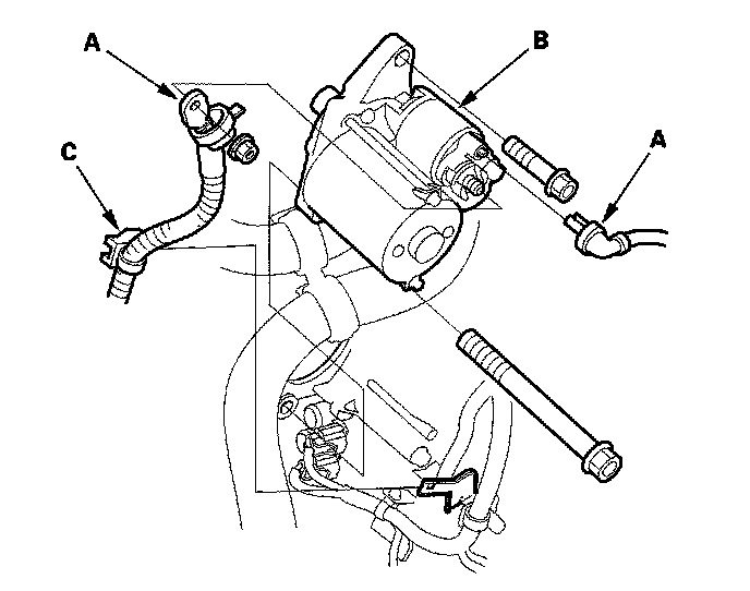
12. Remove the starter.
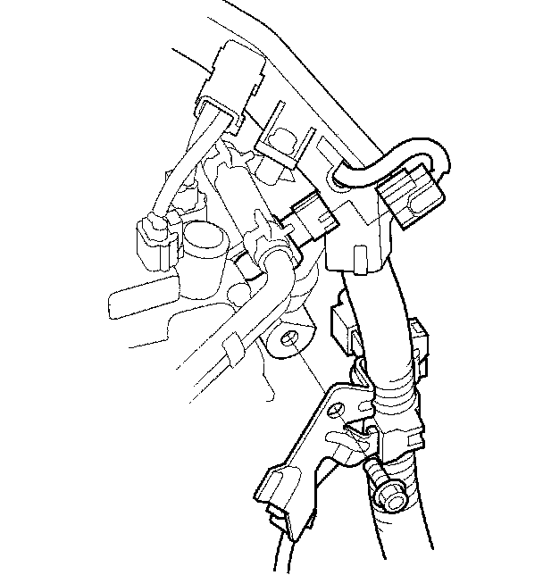
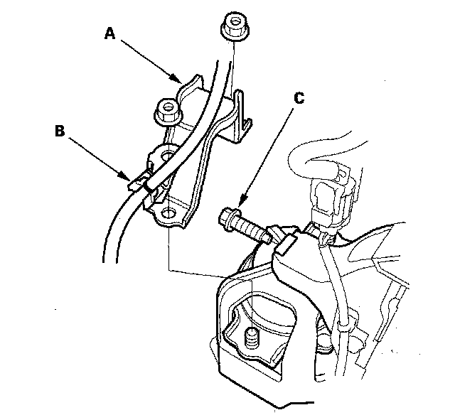
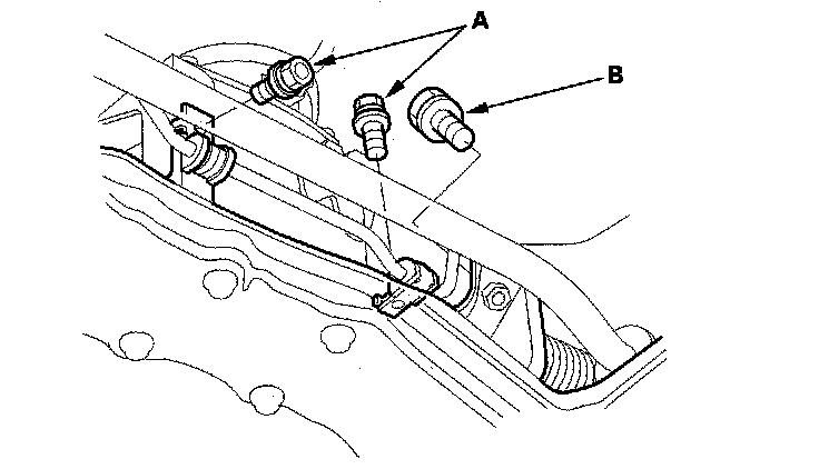
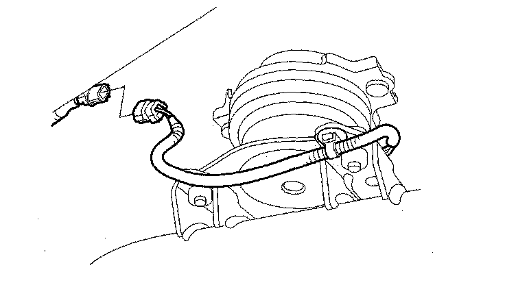
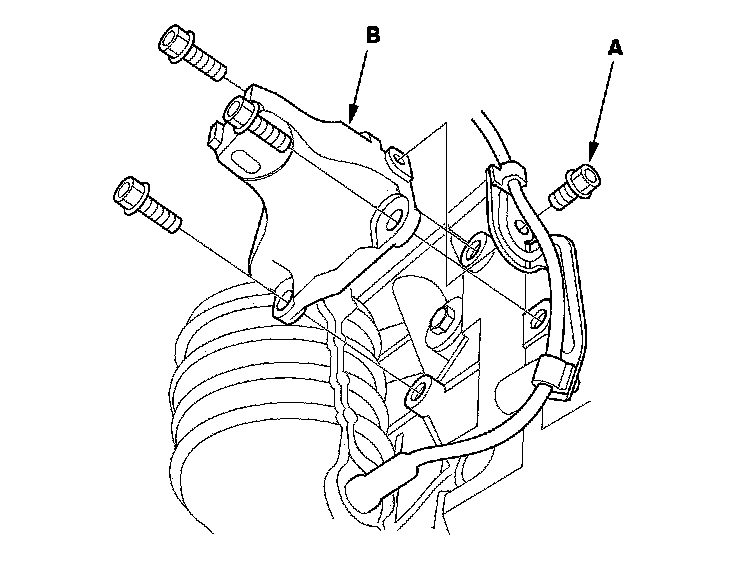
13. Remove the harness clamps (A) from the clamp bracket (B), and disconnect the connectors from shift solenoid valve A (C), shift solenoid valve C (D), A/T clutch pressure control solenoid valve C (E), input shaft (mainshaft) speed sensor (F), and 4th clutch transmission fluid pressure switch (G).
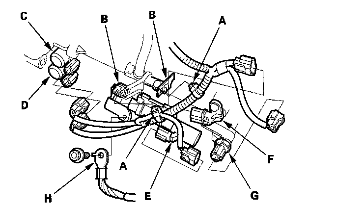
14. Remove the transmission ground terminal (H).
15. Disconnect transmission subharness 6P connector (A), and remove the harness clamps (B).
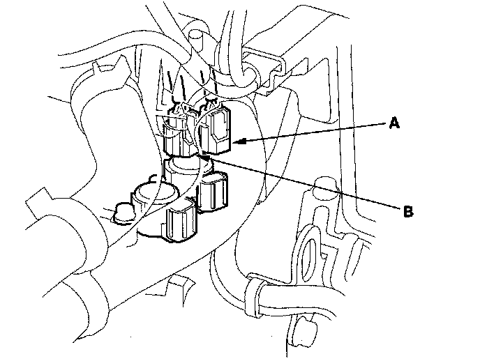
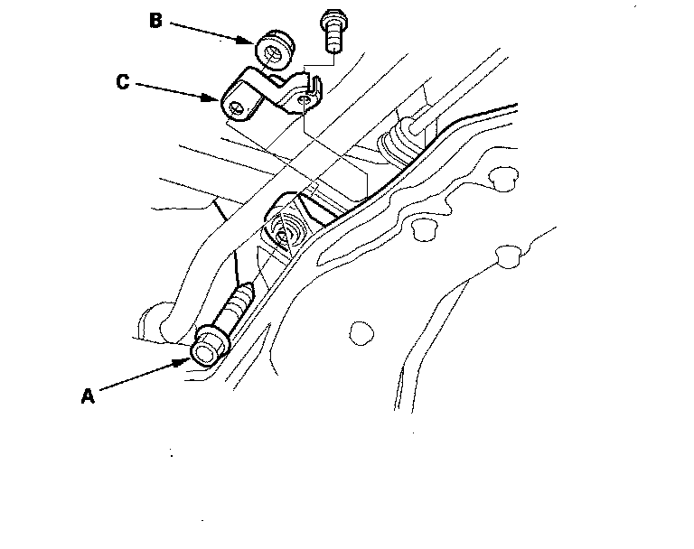
16. Disconnect shift solenoid valve B connector and torque converter clutch solenoid valve connector (A).
17. Remove the transmission range switch connector (A) from its bracket (B), and disconnect it.
18. Disconnect the output shaft (countershaft) speed sensor connector (C).
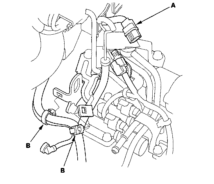
19. Remove the bolt securing the harness cover bracket (D), and separate the harness cover (E) from the cover bracket (F).
20. Remove the connector bracket from the engine front cylinder head; use the bracket bolt hole to attach engine hanger balancer bar front arm.
21. Remove the harness clamp bracket from the engine rear cylinder head; use the bracket bolt hole to attach engine hanger balancer bar rear arm.
22. Remove the front bulkhead cover.
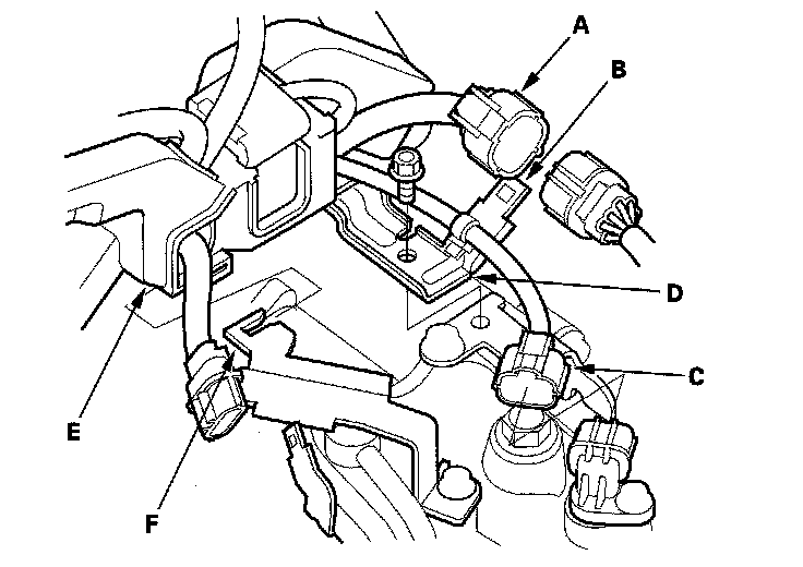
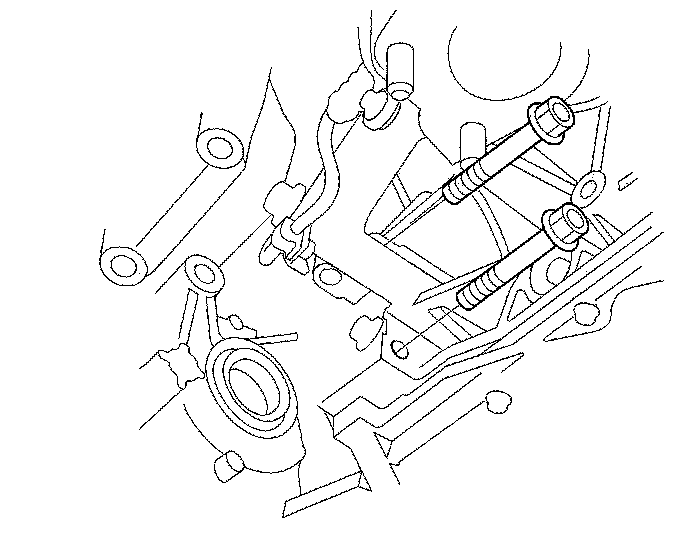
23. Install the engine hanger adapters (VSB02C000022) on the end of the engine support beams (A), then install the engine support hanger (AAR-T-12566) with the adapters to the vehicle.
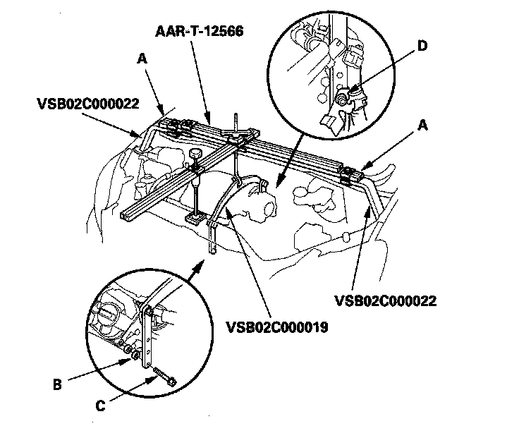
24. Lift and support the engine with the engine support hanger and engine balancer bar (VSB02C000019). Attach the front arm to the front cylinder head with a spacer (B) and the 10 x 1.25 mm bolt (C). Attach the rear arm to the rear cylinder head with the 8 x 1.25 mm bolt (D).
25. For model with active engine mount control system: Remove the front engine mount stop (A), and remove the front engine mount bolt (B).
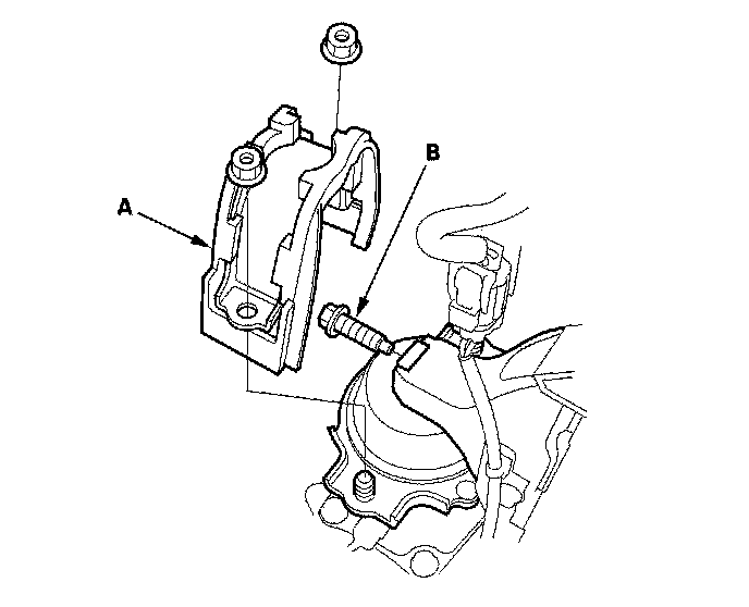
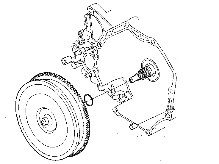
26. For model with engine mount control system: Remove the front engine. mount stop (A), and vacuum tube clamp bracket (B), and remove the front engine mount bolt (C).
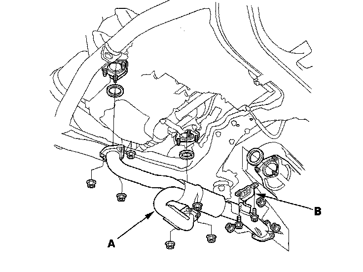
27. Remove the exhaust pipe A and its mount (B).
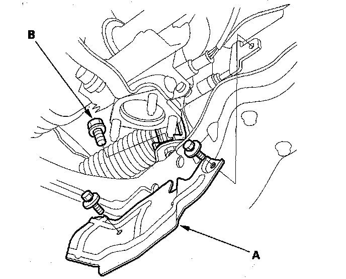
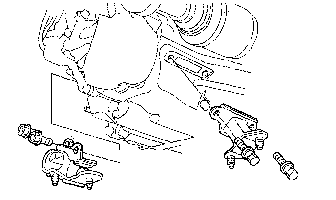
28. Remove the lock pins (A) and castle nuts (B), and separate the lower arms (C) from the knuckles (D).
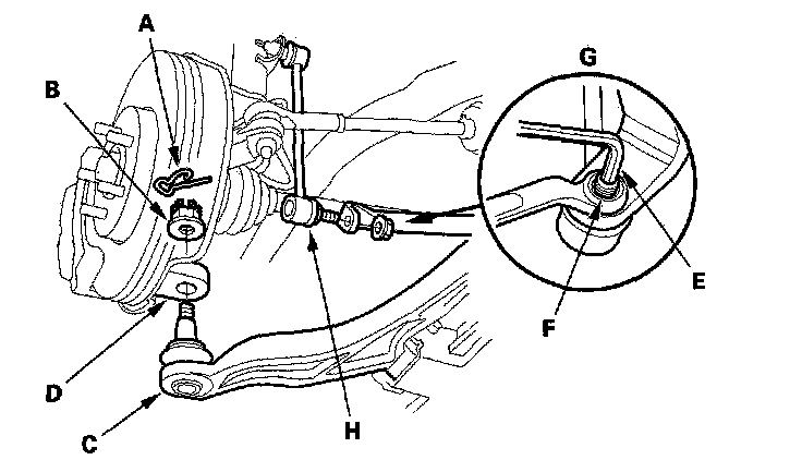
29. Insert a 6 mm Allen wrench (E) in the top of the joint pin (F), remove the nuts (G), then separate the stabilizer links (H).
30. Remove the bolts securing the shift cable holder (A), then remove the shift cable cover (B).
31. Remove the lock bolt (C) securing the control lever (D), and remove the shift cable (E) and the control lever. Do not bend the shift cable excessively.
32. Install 6 x 1.0 - 14 mm bolt (A) and nut (B) on the shift cable cover (C), and reinstall the shift cable cover to the torque converter housing. If you don't do this, the bolt head of the cable cover may prevent you from removing the torque converter during transmission removal.
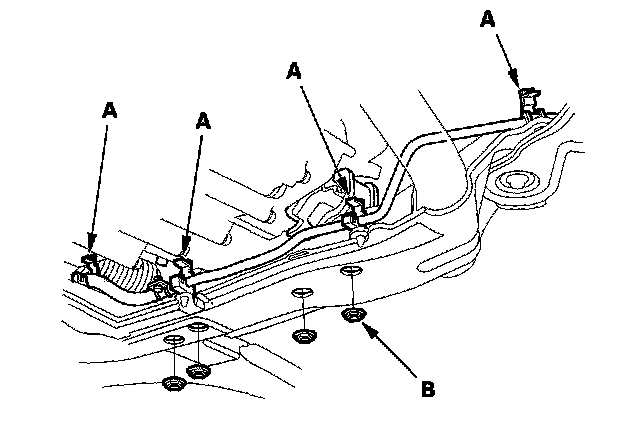
33. Remove the torque converter cover (A), and remove the drive plate bolts (B) (8) while rotating the crankshaft pulley.
34. Remove the engine-to-torque converter housing mounting bolts.
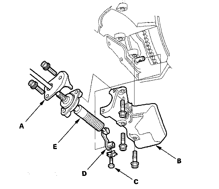
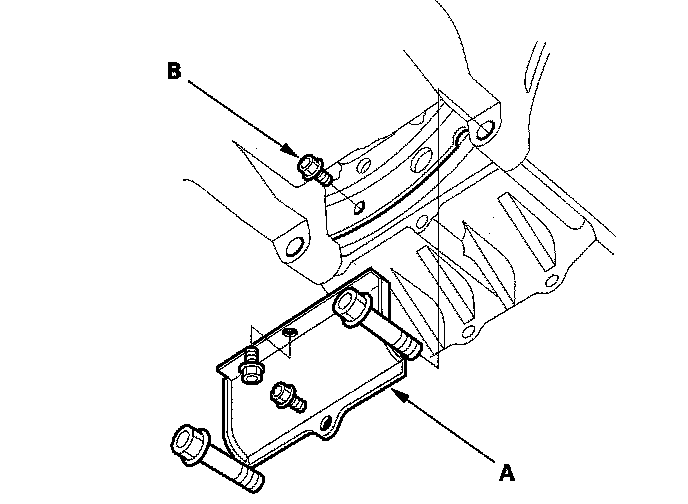
35. Remove the power steering fluid line bracket bolts (A), and remove the steering gearbox mounting bolt (B).
36. Remove the steering gearbox mounting bolt (A) and nut (B), and remove the steering gearbox stiffener (C).
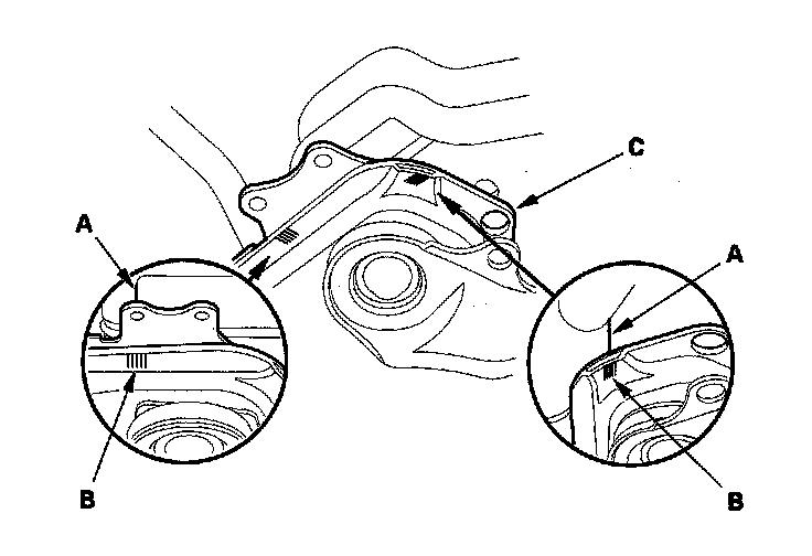
37. Remove the heat shield (A), and remove the steering gearbox. mounting bolt (B).
38. Remove the steering gearbox mounting bolt (A) and nut (B), and remove the steering gearbox stiffener (C).
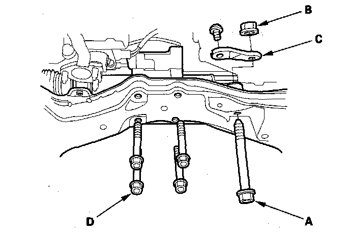
39. Remove the rear mount mounting bolts (D).
40. Unclamp the power steering fluid line clamps, (A) on the front subframe.
41. Remove the transmission lower mount nuts (B).
42. For model with active engine mount control system: Disconnect engine mount control solenoid valve connector at the front engine mount.
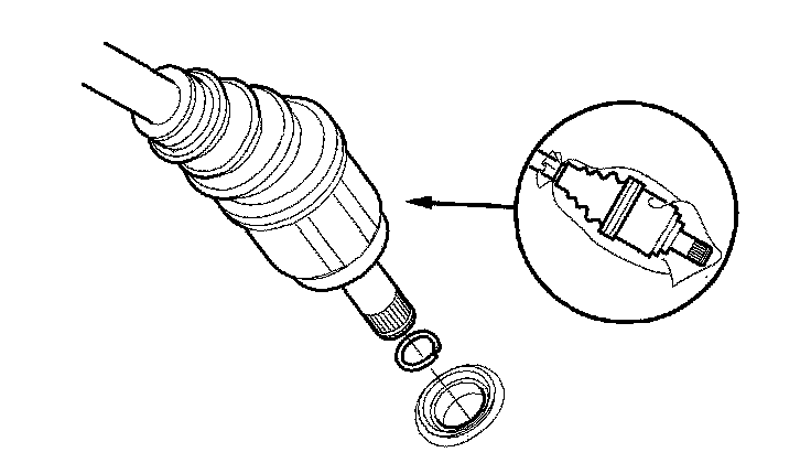
43. For model with engine mount control system: Remove the vacuum tube joint (A) from its clamp (B) from the front engine mount, disconnect the vacuum tube joint, then reinstall the joint in the clamp.
44. Make reference marks (A) on the body across the marks (B) on the edge of the front subframe (C).
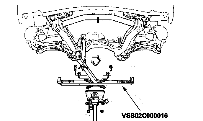
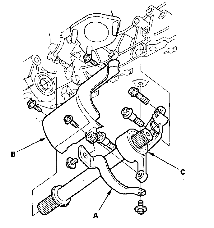
45. Attach the front subframe adapter (VSB02C000016) to the front subframe by looping the belt over the front of the subframe, then securing the belt with its stop.
46. Raise the jack and line up the slots in the arms with the bolt holes on the corner of the jack base, then attach them with bolts.
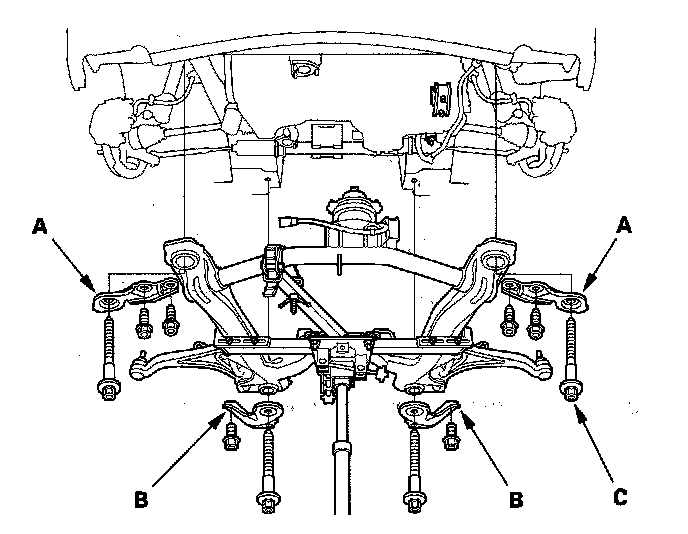
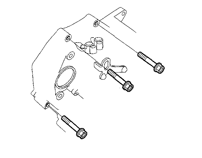
47. Remove the four bolts securing the front stiffeners (A), two bolts securing the rear stiffeners (B), subframe mounting bolts (C), and remove the front and rear stiffeners.
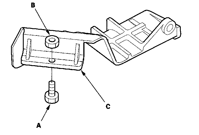
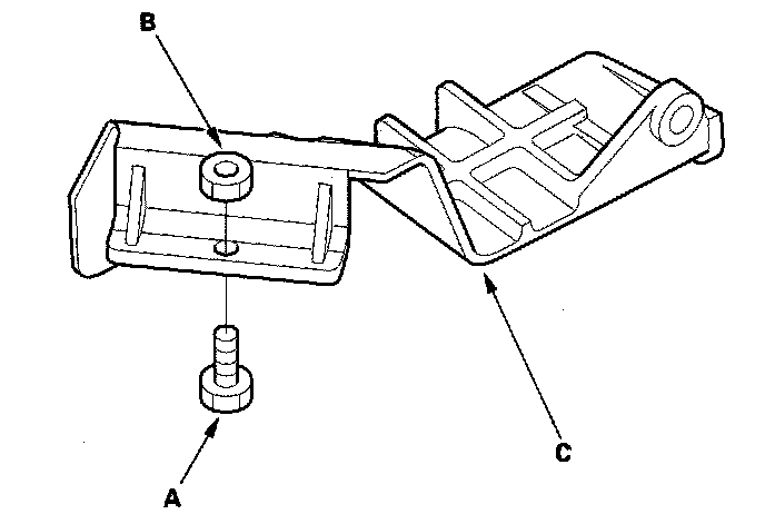
48. Lower the front subframe with the jack.
49. Remove the transmission lower mounts.
50. Remove the left driveshaft from the differential and the right driveshaft from the intermediate shaft.
51. Move the left driveshaft to the front side. Coat all precision finished surfaces with clean engine oil, then put plastic bags over the driveshaft ends.
52. Remove the rear warm up three way catalytic converter (WU-TWC) stay (A) and heat shield (B).
53. Remove the intermediate shaft (C). Coat all precision finished surfaces with clean engine oil, then put plastic bags over the intermediate shaft ends.
54. Remove the upper and front transmission housing mounting bolts.
55. Remove the bolt (A) securing the harness clamp bracket, and remove the front mount bracket (B).
56. Remove the rear transmission housing mounting bolts.
57. Slide the transmission away from the engine to remove it from the vehicle, and lower it on the transmission jack. If the torque converter is stuck to the drive plate, pull it toward the transmission housing through the starter opening.
58. Remove the shift cable cover, then remove the torque converter assembly from the torque converter housing.
59. Inspect the drive plate, and replace it if it is damaged'.
60. Remove the 6 x 1.0 - 14 mm bolt (A) and nut (B) from the shift cable cover (C).