Antilock Brakes / Traction Control Systems: Description and Operation
System DescriptionSystem Outline
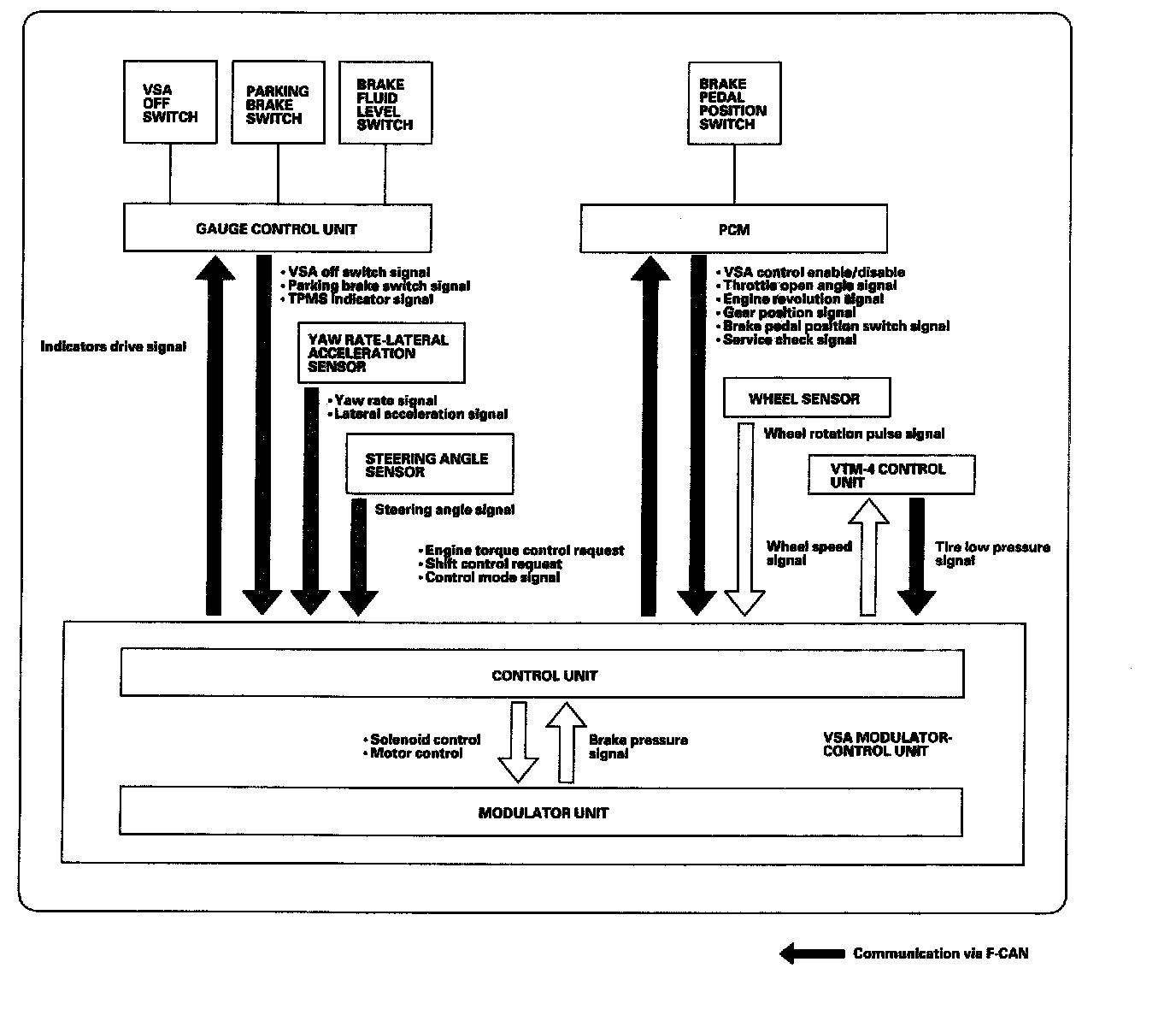
This system is composed of the VSA modulator-control unit, the wheel sensor, steering angle sensor, and yaw rate lateral acceleration sensor, and takes charge of the ABS, EBD, TCS, VSA, and brake assist control by controlling the brake pressure of each wheel and the engine torque.
ABS Features
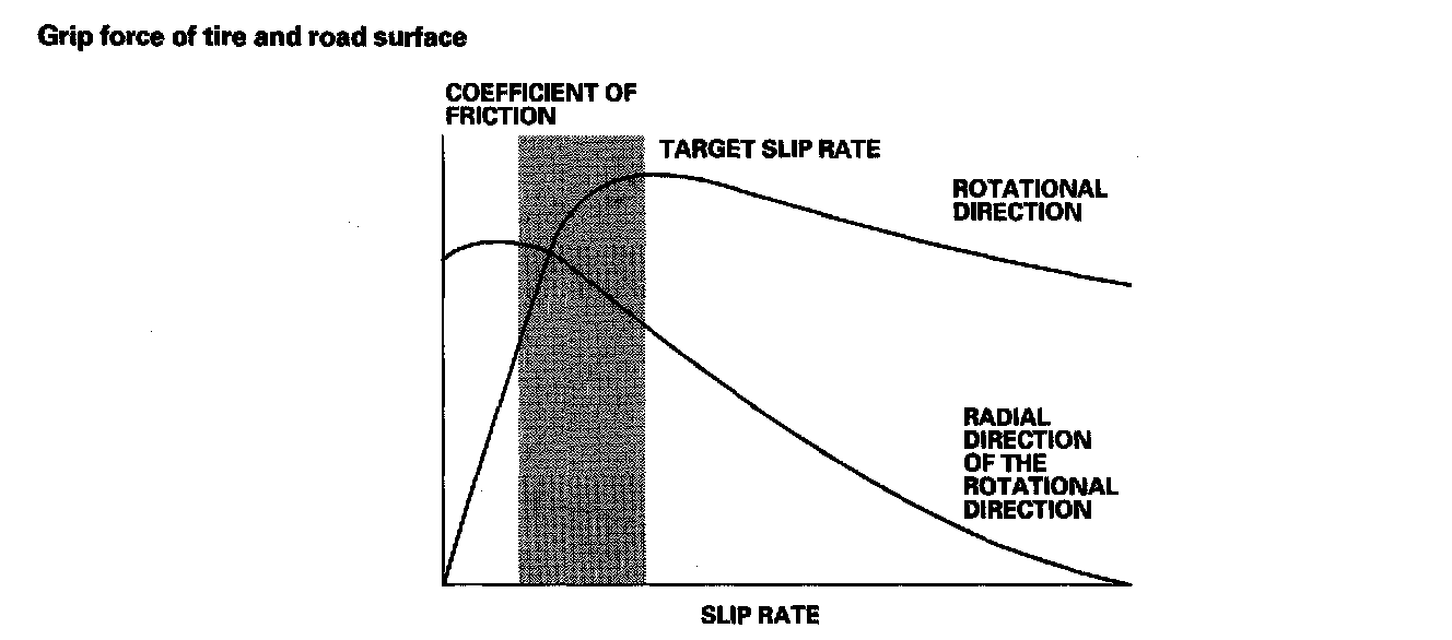
When the brake pedal is pressed while driving, the wheels sometimes lock before the vehicle comes to a stop. In such an event, the maneuverability of the vehicle is reduced if the front wheels are locked, and the stability of the vehicle is reduced if the rear wheels are locked, creating an extremely unstable condition. The ABS precisely controls the slip rate of the wheels to ensure maximum grip force from the tires, and it thereby ensures maneuverability and stability of the vehicle. The ABS calculates the slip rate of the wheels based on the four wheel speed, then it controls the brake fluid pressure to reach the target slip rate.
Grip Force Of Tire And Road Surface:
EBD Features
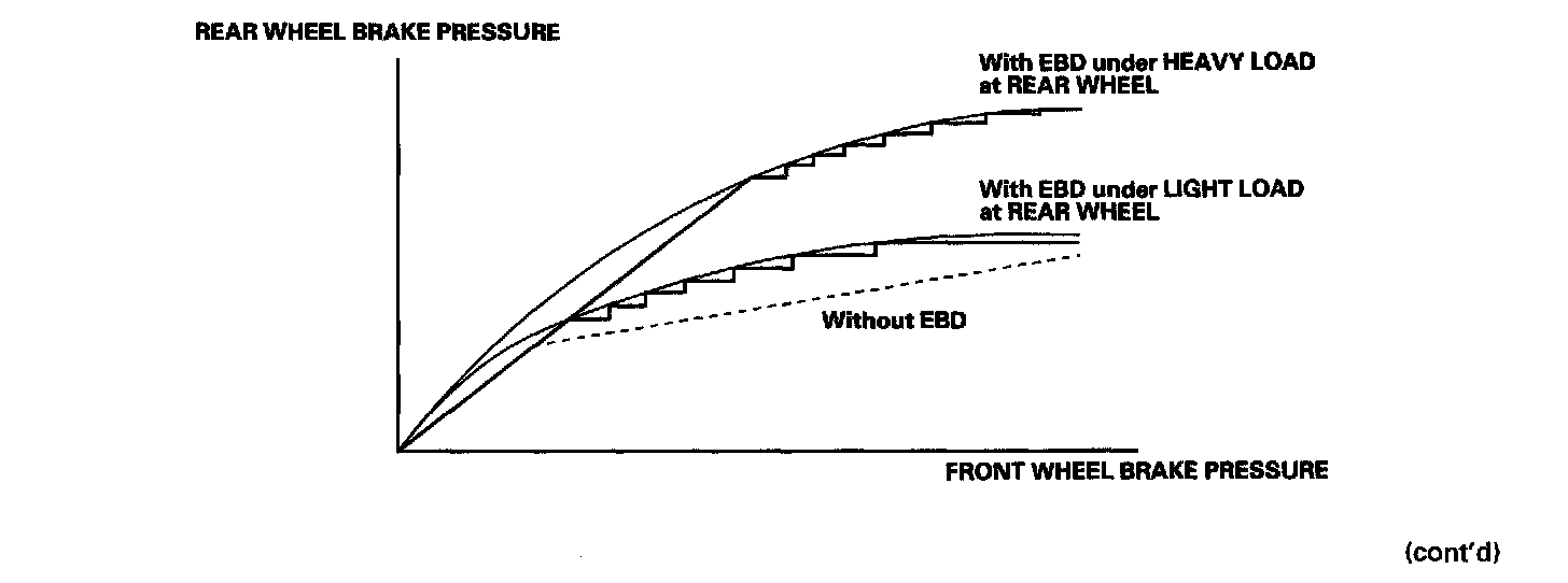
The electronic brake distribution (EBD) helps control vehicle braking by adjusting the rear brake force in accordance with rear wheel load before the ABS operates. Based on wheel sensor signals, the ABS control unit uses the modulator to control the rear brakes individually. When the rear wheel speed is less than the front wheel speed, the VSA modulator-control unit retains the current rear brake fluid pressure by closing the inlet valve in the modulator. As the rear wheel speed increases and approaches the front wheel speed, the VSA modulator-control unit increases the rear brake fluid pressure by momentarily opening the inlet valve. This whole process is repeated very rapidly. While this is happening, there is kickback at the brake pedal.
TCS Features
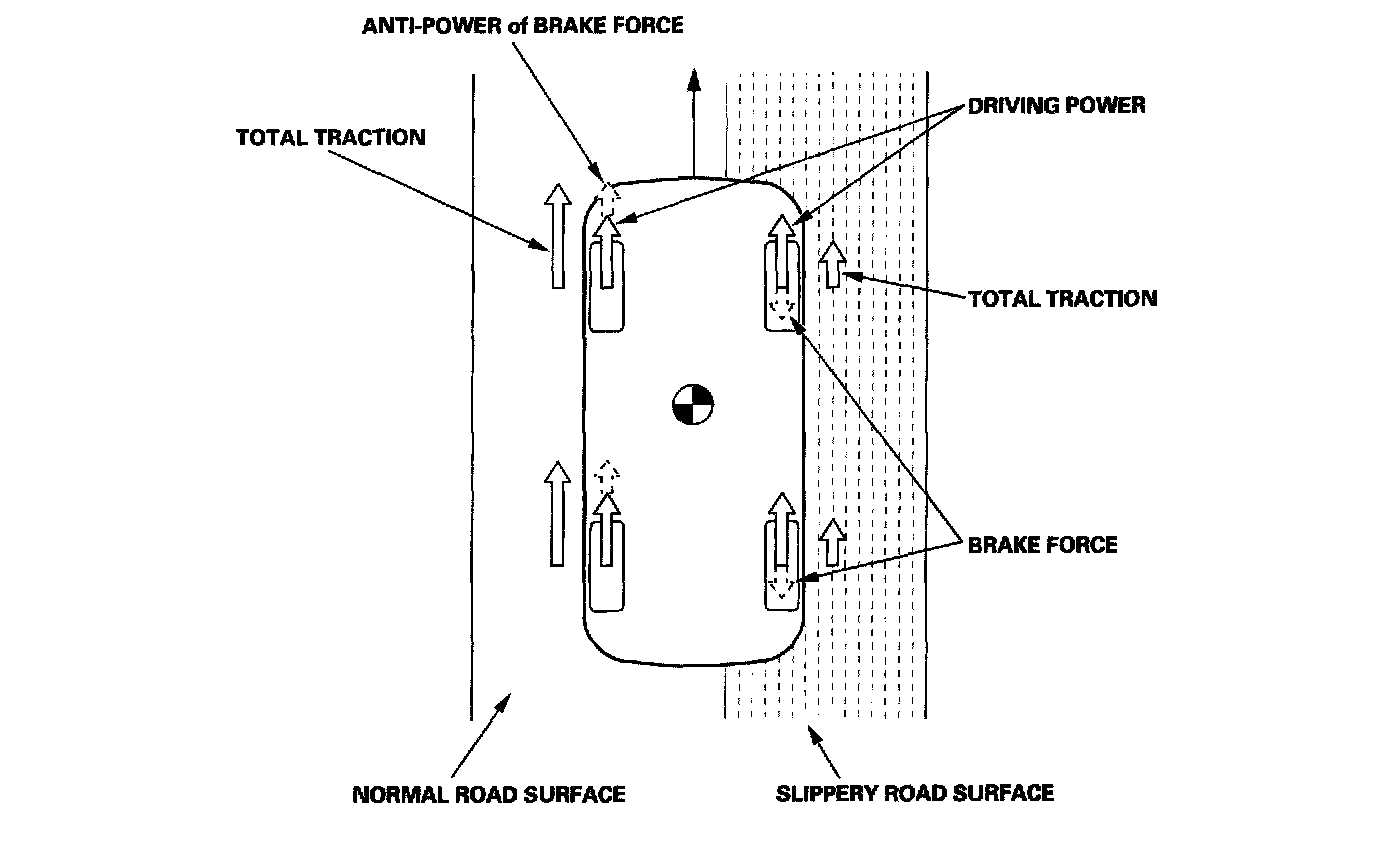
When a drive wheel loses traction on a slippery road surface and starts to spin, the VSA modulator-control unit applies brake pressure to the spinning wheel and sends engine torque control request to the PCM to slow the spinning wheel and keep traction.
VSA System Features
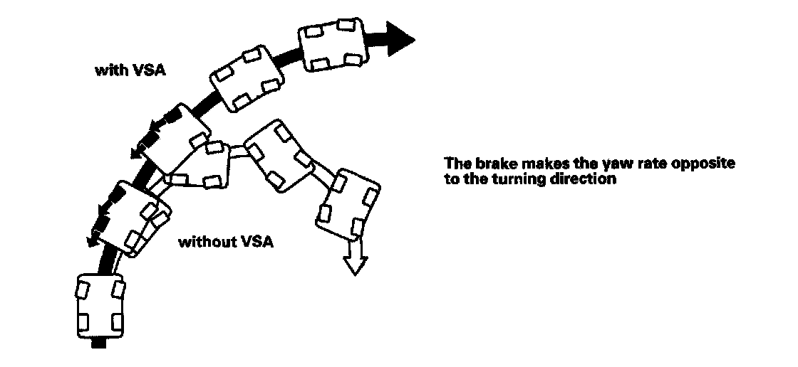
Oversteer control
Applies the brake to the front and rear outside wheels
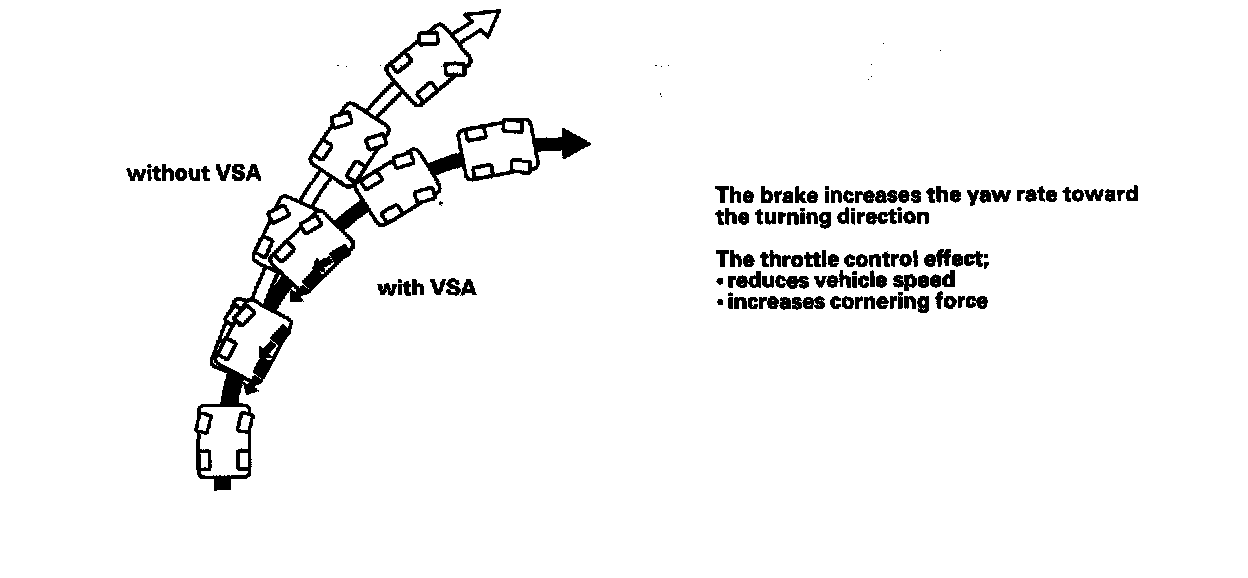
Understeer control
^ Applies the brake to the front and rear inside wheels
^ Controls the engine torque when accelerating
Brake Assist Features
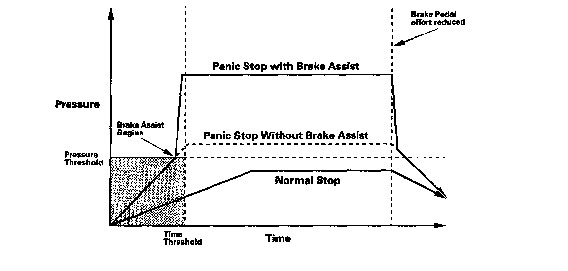
Brake assist helps ensure that any driver can achieve the full braking potential of the vehicle by increasing brake system pressure in a panic situation, bringing the vehicle into a full ABS stop. Each time the ignition switch is turned ON (II), the VSA modulator-control unit learns the current driver's normal braking characteristics by monitoring the brake pressure sensor and the brake pedal position switch at each stop. Using these inputs and their values, the VSA modulator-control unit is able to learn the driver's normal braking habits, and then determine the difference between a normal stop and a panic stop for the individual driver of the vehicle. If during a panic stop the VSA modulator-control unit determines that the brake system pressure increases above a learned threshold in less than a learned amount of time, the VSA modulator-control unit engages brake assist. Because the brake system pressure crossed the threshold before the time threshold had expired, the VSA modulator-control unit goes into brake assist mode.
Modulator Unit
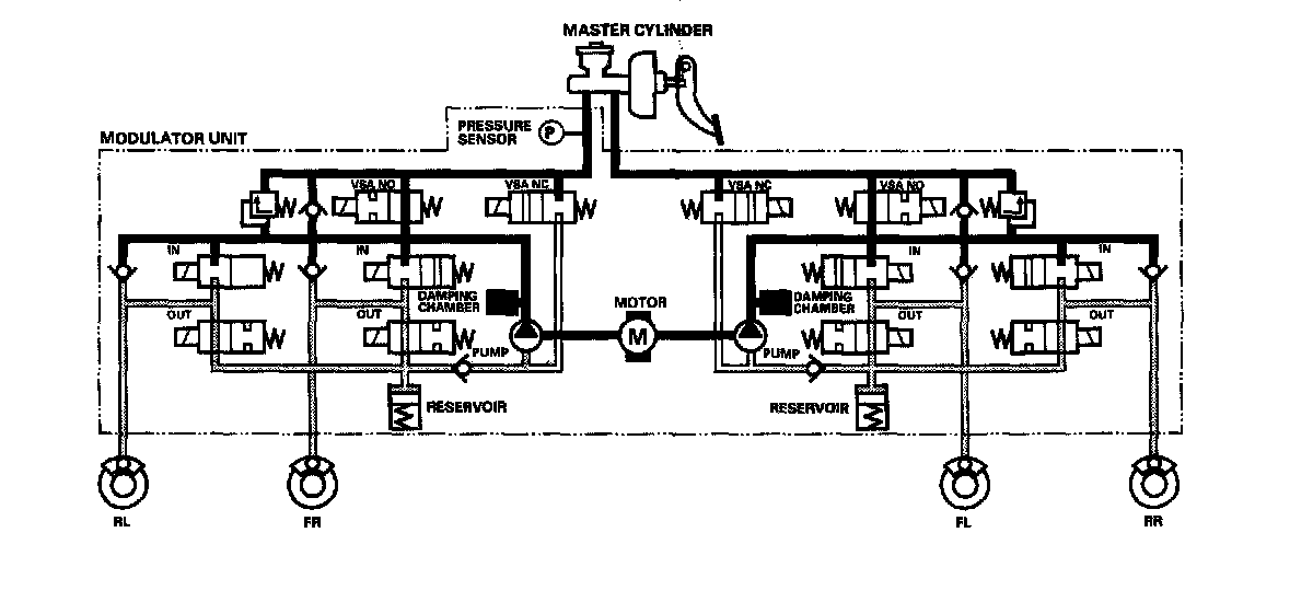
The modulator unit consists of the inlet solenoid valve, the outlet solenoid valve, the VSA normally open (NO) solenoid valve, VSA normally closed (NC) solenoid valve, the reservoir, the pump, the pump motor, and the damping chamber.
The modulator controls the caliper fluid pressure directly. It is a circulating-type modulator because the brake fluid circulates through the caliper, the reservoir, and the master cylinder.
The hydraulic control has three modes: pressure intensifying, pressure retaining, and pressure reducing.
The hydraulic circuit is an independent four channel type, one channel for each wheel.
ABS Control
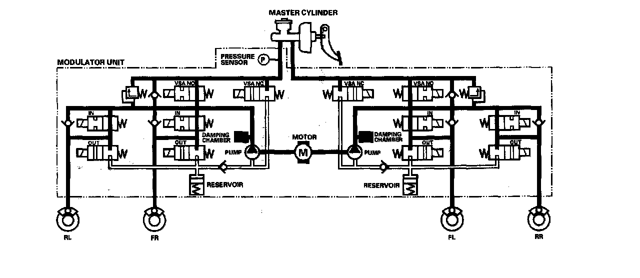
Pressure intensifying mode
VSA NO valve open, VSA NC valve closed, inlet valve open, outlet valve closed. Master cylinder fluid is pumped out to the caliper.
Pump motor
When starting the pressure reducing mode, the pump motor is ON. When stopping ABS operation, the pump motor is OFF.
The reservoir fluid is pumped out by the pump, through the damping chamber, to the master cylinder.
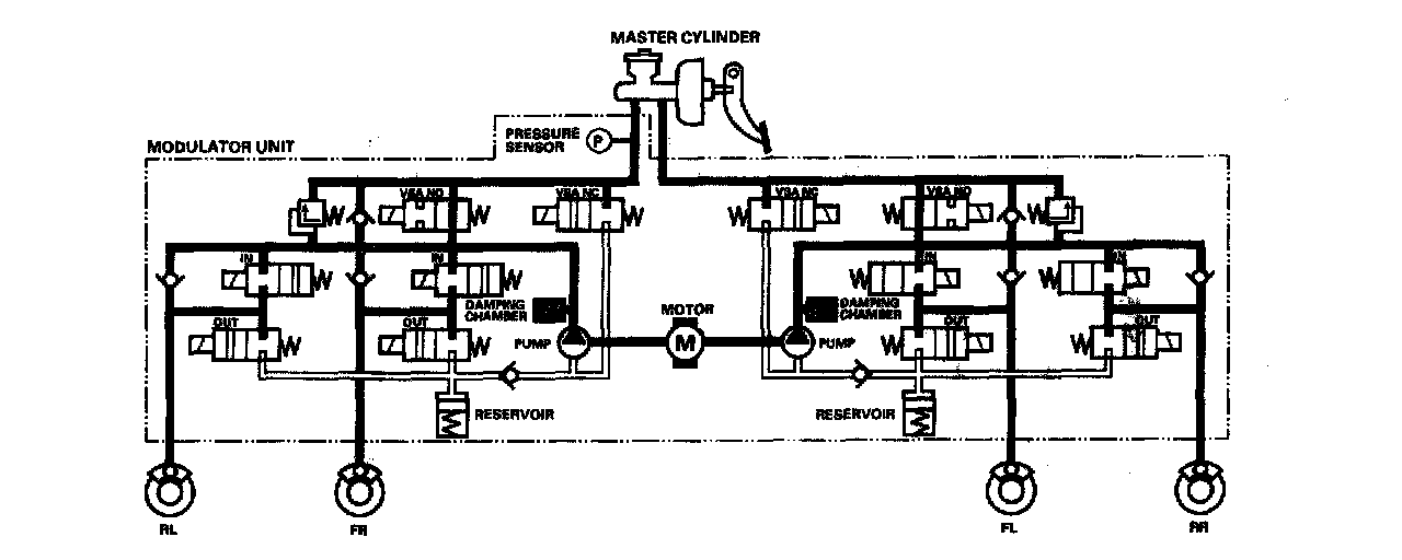
Pressure retaining mode
VSA NO valve open, VSA NC valve closed, inlet valve closed, outlet valve closed.
Caliper fluid is retained by the inlet valve and outlet valve.
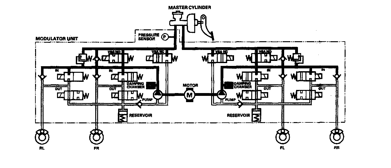
Pressure reducing mode
VSA NO valve open, VSA NC valve closed, inlet valve closed, outlet valve open.
Caliper fluid flows through the outlet valve to the reservoir.
TCS Control
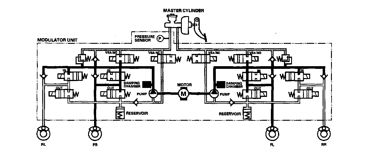
Pressure intensifying mode
VSA NO valve closed, VSA NC valve open, inlet valve open, outlet valve closed, pump motor ON.
The reservoir and master cylinder fluid is pumped out by the pump, through the damping chamber, to the front caliper.
Pressure retaining mode
VSA NO valve closed, VSA NC valve open, inlet valve closed, outlet valve closed, pump motor ON.
Front caliper fluid is retained by the inlet valve and outlet valve.
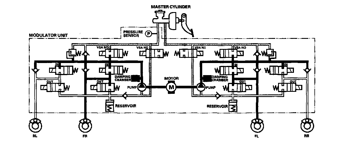
Pressure reducing mode
VSA NO valve open, VSA NC valve closed, inlet valve closed, front outlet valve open, pump motor ON.
Caliper fluid flows through the outlet valve to the reservoir.
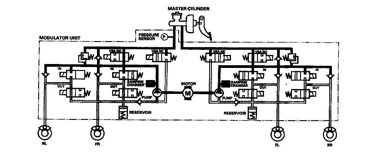
VSA Control
Pressure intensifying mode
VSA NO valve closed, VSA NC valve open, inlet valve open, outlet valve closed, pump motor ON.
The reservoir and master cylinder fluid is pumped out by the pump, through the damping chamber, to the front and rear calipers.
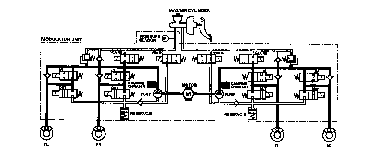
Pressure retaining mode
VSA NO valve closed, VSA NC valve open, inlet valve closed, outlet valve closed, pump motor ON.
Front and rear caliper fluid is retained by the inlet valve and outlet valve.
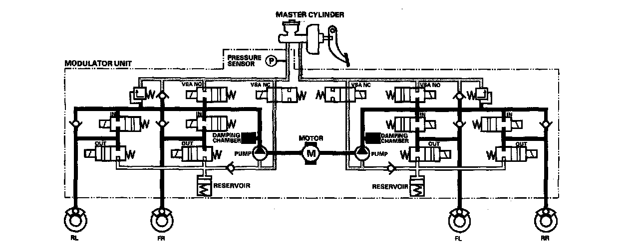
Pressure reducing mode
VSA NO valve open, VSA NC valve closed, inlet valve closed, outlet valve open, pump motor ON.
Caliper fluid flows through the outlet valve to the reservoir.