Transmission Installation
Transmission InstallationSpecial Tools Required
^ Engine support hanger, A and Reds AAR-T1256
^ Engine hanger balancer bar VSB02C000019
^ Engine hanger adapter VSB02C000022
^ Front subframe adapter VSB02C000016
^ 2008 V6 attachment arm SIL02C000033
These special tools are available through the Honda Tool and Equipment Program 1-888-424-6857.
NOTE: Use fender covers to avoid damaging painted surfaces.
1. Clean the ATF cooler.
2. Install the torque converter (A) on the mainshaft (B) with a new O-ring (C).
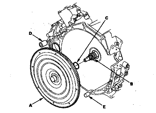
3. Install the 14 mm dowel pin (D) and the 10 mm dowel pin (E) in the torque converter housing.
4. Install the transmission lower mounts.
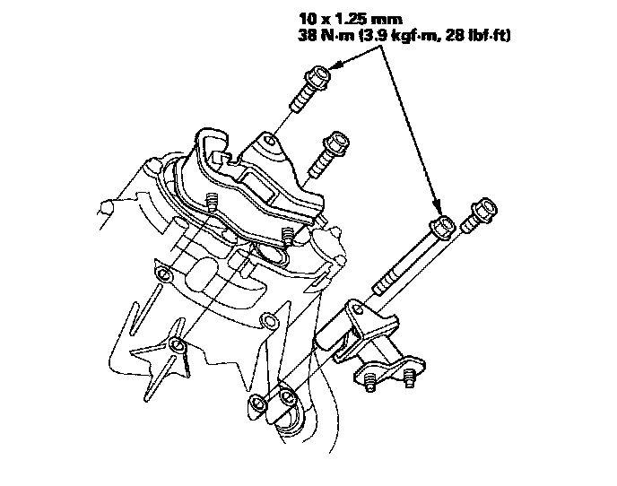
5. Place the transmission on the jack, and raise it to engine level.
6. Attach the transmission to the engine, and install the lower transmission housing mounting bolts.
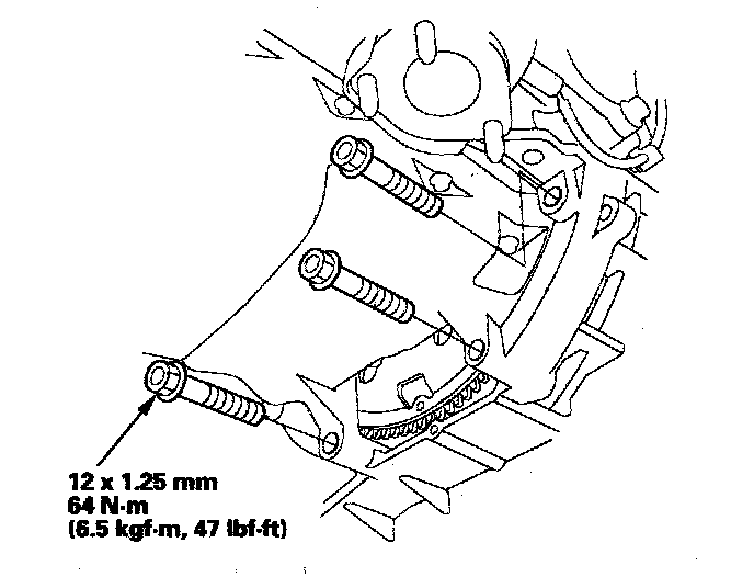
7. Install the rear transmission housing mounting bolts.
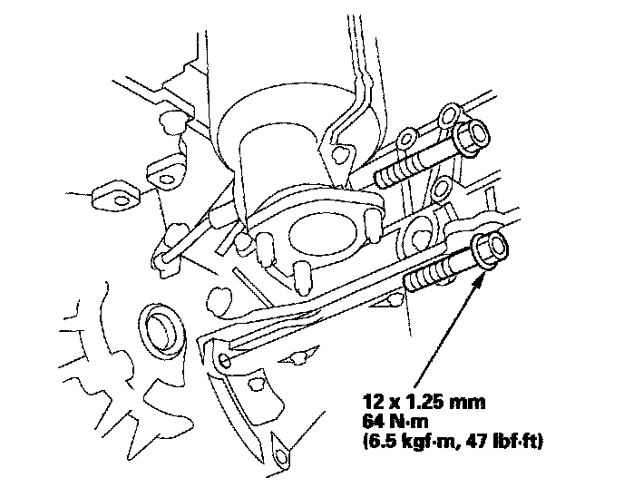
8. Remove the jack from the transmission.
9. Install the transmission housing mounting bolt (A).
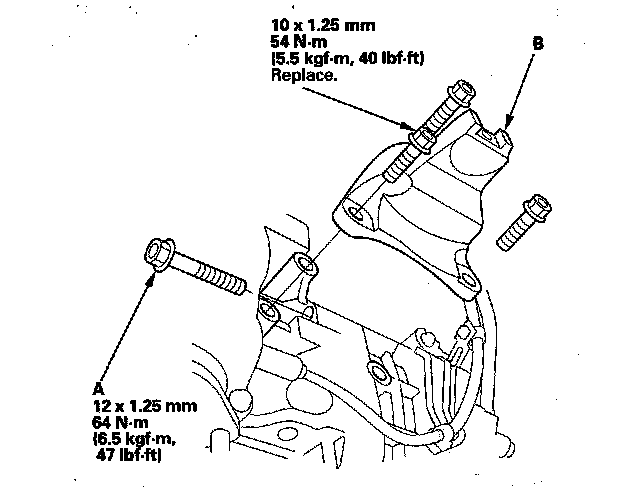
10. Install the front mount bracket (B) with new mounting bolts.
11. Clean the areas where the intermediate shaft and the driveshaft contact the transmission (differential) with solvent and dry with compressed air.
12. Install a new set ring (A) on the intermediate shaft (B), and install the intermediate shaft in the differential. While installing the intermediate shaft in the differential, be sure not to allow dust or other foreign particles to enter the transmission.
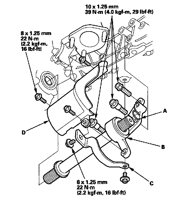
13. Install the rear warm-up three-way catalytic converter (WU-TWC) stay (C) and the heat shield (D).
14. Install a new set ring (A) on the left driveshaft (B).
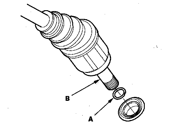
15. Install the right and left driveshaft. While installing the left driveshaft in the differential, be sure not to allow dust or other foreign particles to enter the transmission.
NOTE:
^ Clean the areas where the left driveshaft contacts the transmission (differential) with solvent and dry with compressed air.
^ Turn the right and left steering knuckle fully outward, and slide the left driveshaft into the differential until you feel its set ring engage the side gear. Slide the right driveshaft over the intermediate shaft splines until you feel the driveshaft engage the intermediate shaft set ring.
16. Support the front subframe (A) with the front subframe adapter (VSB02C000016) and a jack, and lift it up to body.
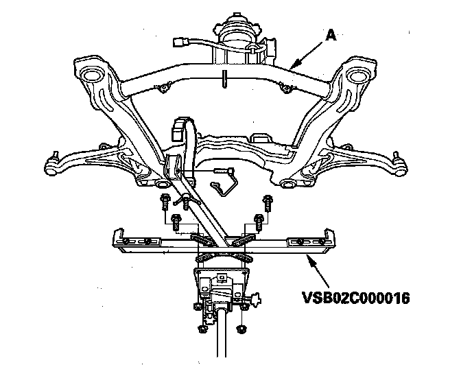
17. Loosely install new subframe mounting bolts (A), the front stiffener mounting bolts (B), the rear stiffener mounting bolts (C), and the front and rear stiffeners.
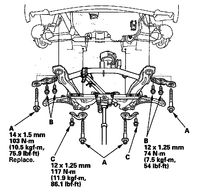
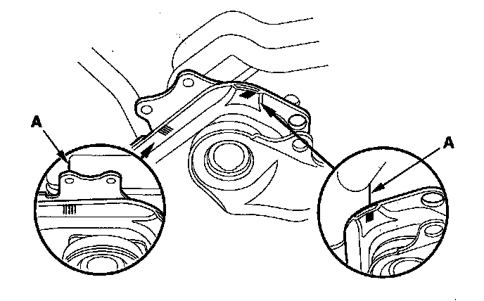
18. Align all reference marks (A) on the body and the subframe. Tighten the rear subframe mounting bolts, then the front bolts, and tighten the stiffener bolts to the specified torque.
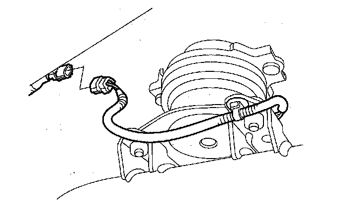
19. With active engine mount control system: Connect engine mount control solenoid valve connector.
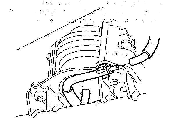
20. With engine mount control system: Connect the vacuum tube joint and install the joint in the clamp at the engine mount.
21. Install the transmission lower mount nuts.
22. Install the power steering fluid line (A) on the clamps (B).

23. Install a new rear mount mounting bolts.
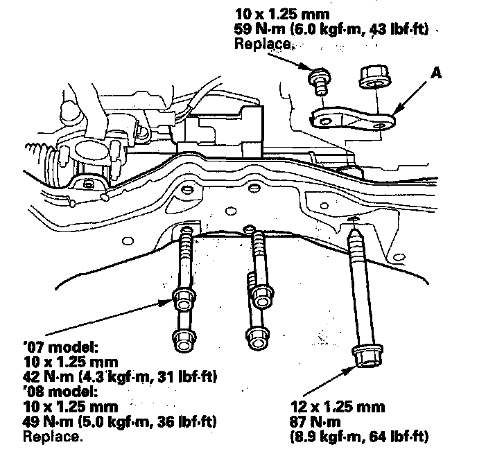
24. Install the steering gearbox stiffener (A), and loosely install the bolts.
25. Install the steering gearbox stiffener (A), and loosely install the bolts.
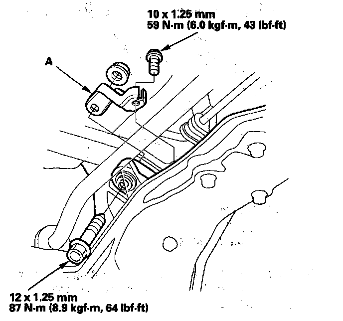
26. Install the steering gearbox mounting bolt and the heat shield (A).
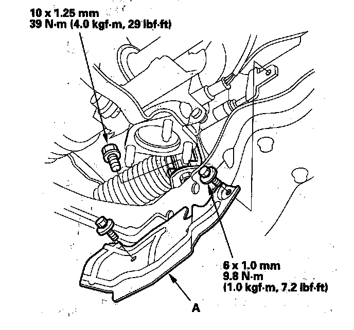
27. Install the steering gearbox mounting bolt (A) and the power steering fluid line bracket bolts (B), (C) ('07 model).
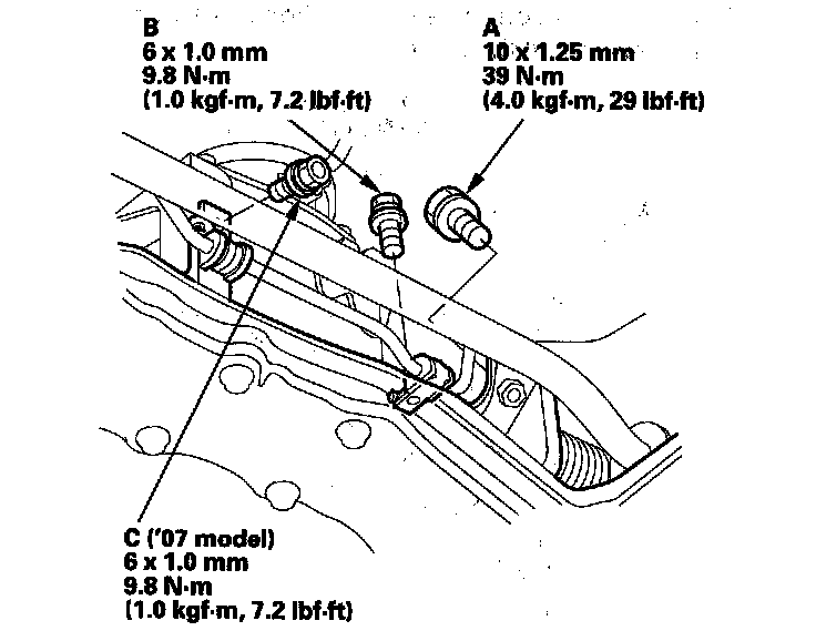
28. Tighten the steering gearbox mounting bolts and the gearbox stiffener mounting bolts to the specified torque.
29. Attach the torque converter to the drive plate (A) with the eight bolts (B). Rotate the crankshaft pulley as necessary to tighten the bolt to 1/2 of the specified torque, then to the final torque, in a crisscross pattern. After tightening the last bolt, check that the crankshaft rotates freely.
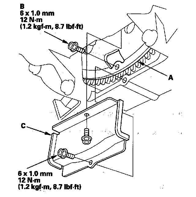
30. Install the torque converter cover (C).
31. Install the ball joint on each lower arm (A) with a new castle nut (B) and a new lock pin (C).
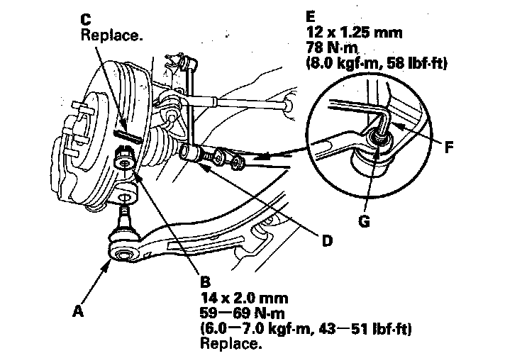
32. Install the stabilizer links (D) to the lower arms, and install the nuts (E). Insert a 6 mm alien wrench (F) in the ball joint pin (G), and lightly tighten the nuts.
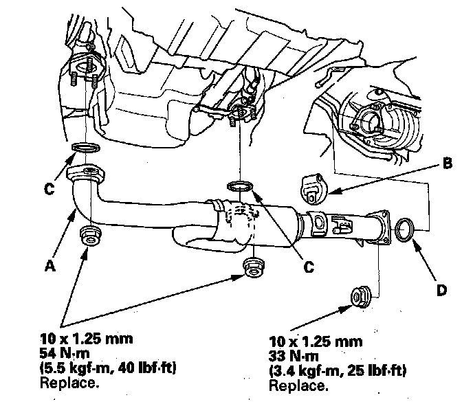
33. Install exhaust pipe A with new self-locking nuts, its mount (B), and new gaskets (C) (D).
34. With active engine mount control system: Install a new front engine mount bolt, and install the front engine mount stop.
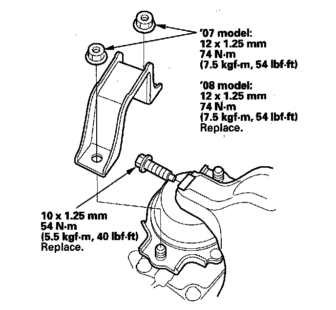
35. With engine mount control system: Install a new front engine mount bolt, and install the front engine mount stop (A) and the vacuum tube clamp bracket (B).
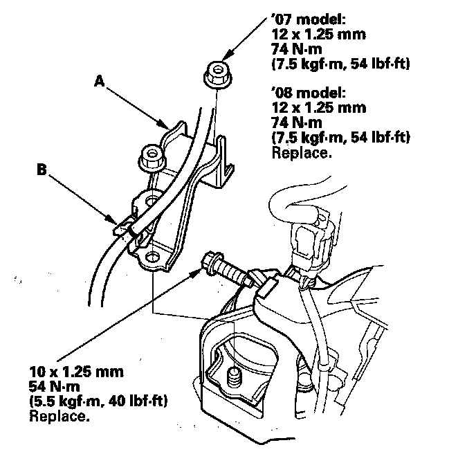
36. Remove the engine support hanger and the engine balancer bar.
37. Install the front A/F sensor connector bracket to the engine front cylinder head.
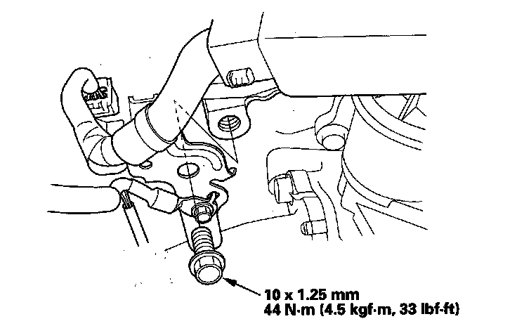
38. Install the rear A/F sensor connector bracket on the rear cylinder head.
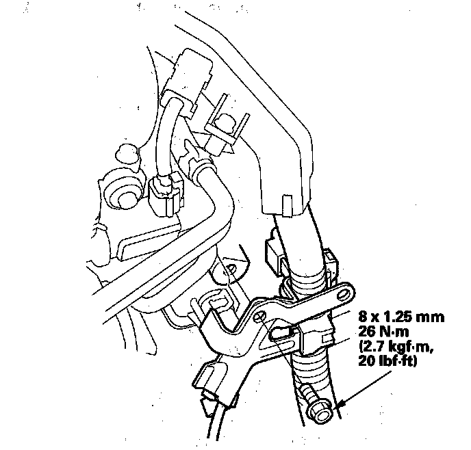
39. Install the upper transmission housing mounting bolts.
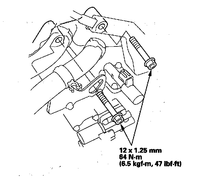
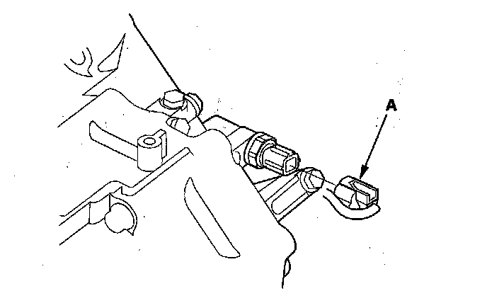
40. Connect the 2nd clutch transmission fluid pressure switch connector (A).
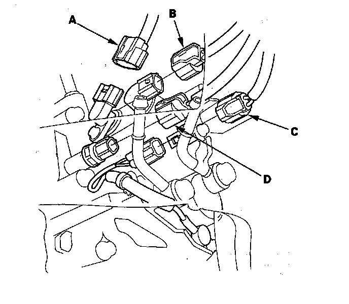
41. Connect the input shaft (mainshaft) speed sensor connector (A), the output shaft (countershaft) speed sensor connector (B), the ATF temperature sensor connector (C), and the 3rd clutch transmission fluid pressure switch connector (D). Do not allow water, fluid, oil, dust, or other foreign particles to enter any of the connectors.
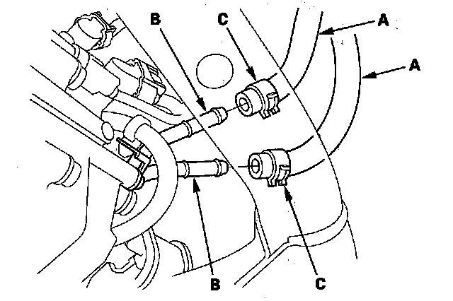
42. Connect the ATF cooler hoses (A) to the ATF cooler lines (B), and secure the hoses with the clips (C).
43. Connect the transmission range switch connector (A), and install the harness clamp (B) on the clamp bracket (C).
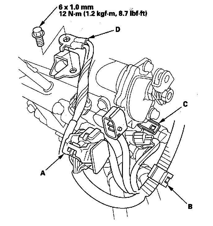
44. Install the transmission ground cable (D).
45. Secure the harness cover (A) and the cover bracket (B) with the bolts.
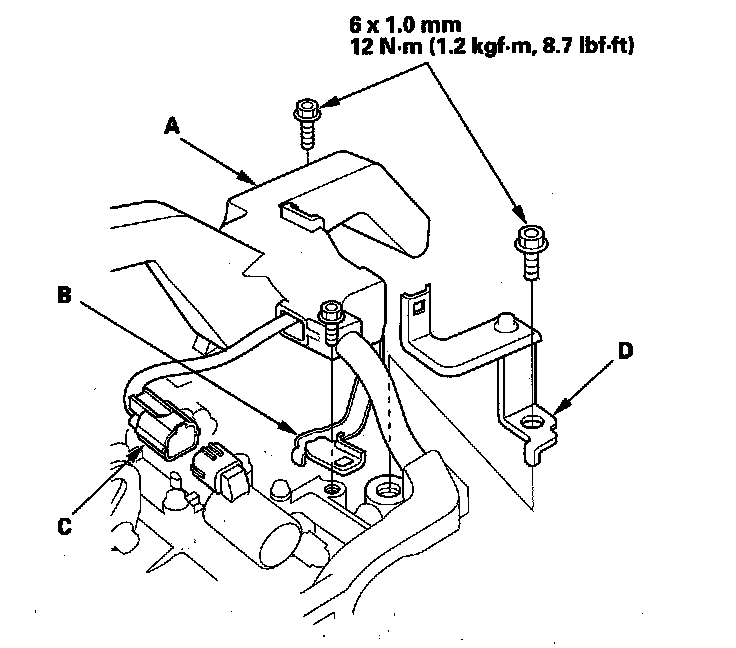
46. Connect the A/T clutch pressure control solenoid valve C connector (C).
47. '08 model with the J35A7 engine: Install the starter cable clamp bracket (D).
48. Install the harness cover (A) on the harness cover/clamp bracket (B), and secure it with the bolt.
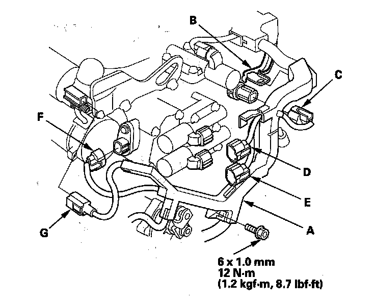
49. Connect the 4th clutch transmission fluid pressure switch connector (C). Connect the A/T clutch pressure, control solenoid valve A connector (D) and the A/T clutch pressure control solenoid valve B connector (E).
50. Connect the shift solenoid harness connector (F) and the S terminal connector (G).
51. Apply molybdenum grease to the hole in the bushing (A) in the shift cable end (B). Attach the shift cable end to the control lever (C), then insert the control pin (D) into the control lever hole through the shift cable end, and secure the control pin with the spring clip (E).
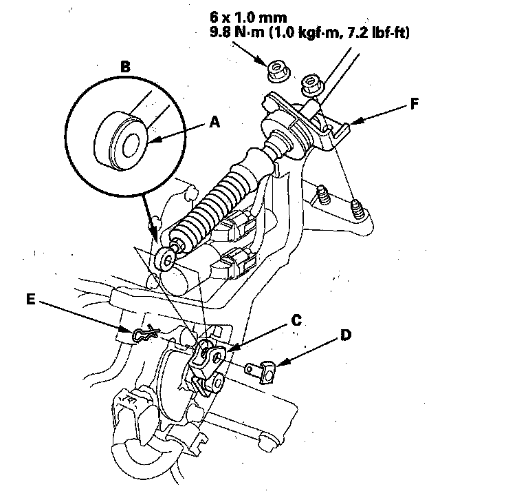
52. Secure the shift cable bracket (F) with the nuts.
53. Install the shift cable on the shift lever, and adjust the cable.
54. Except '08 model with the J35A7 engine: Install the starter (A) and a new gasket (B). Install the mounting bolt (C) through the harness clamp bracket hole (D), and into the lower mounting bolt thread hole (E).
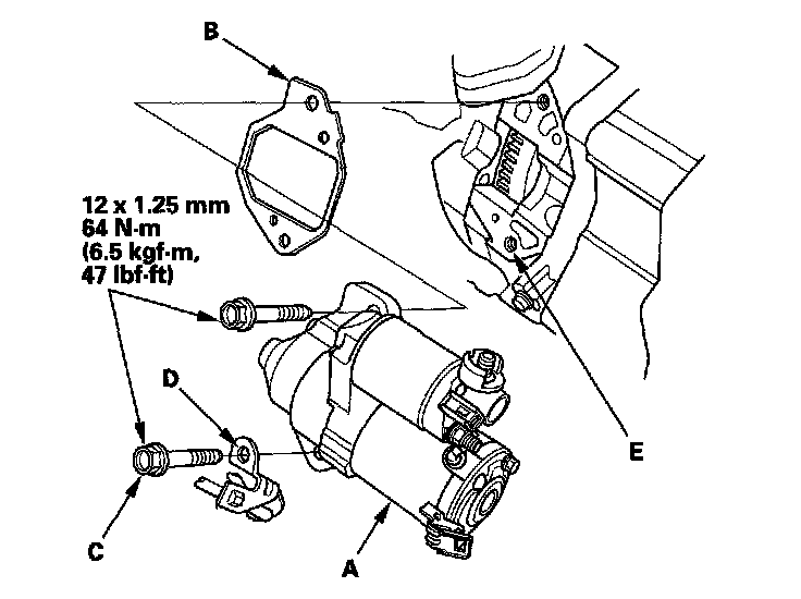
55. '08 model with the J35A7 engine: Install the starter (A) and a new gasket (B).
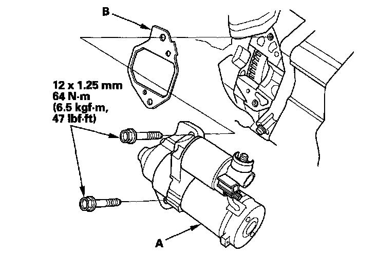
56. Except '08 model with the J35A7 engine: Install the starter cable (A), and install the harness clamp (B) on the clamp bracket (C).
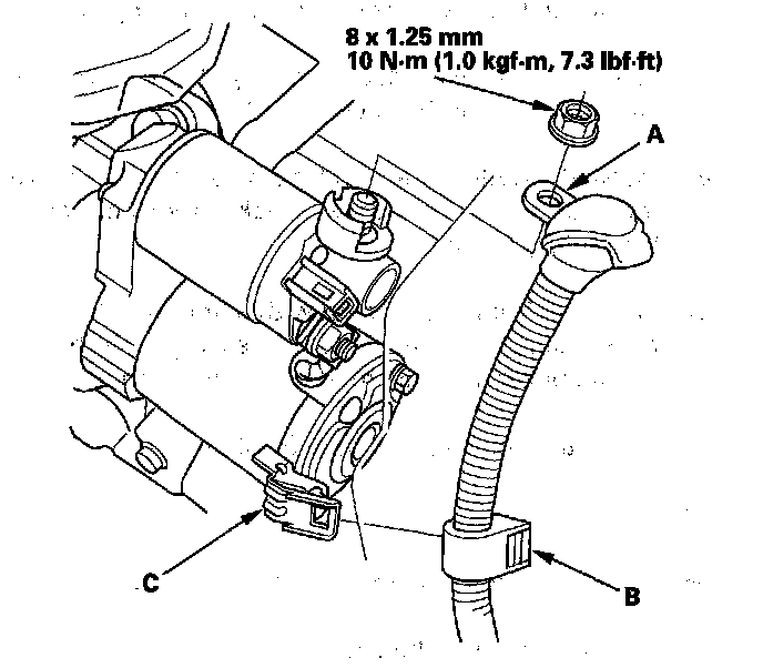
57. '08 model with the J35A7 engine: Install the starter cable (A), and install the harness clamps (B) on the clamp brackets (C).
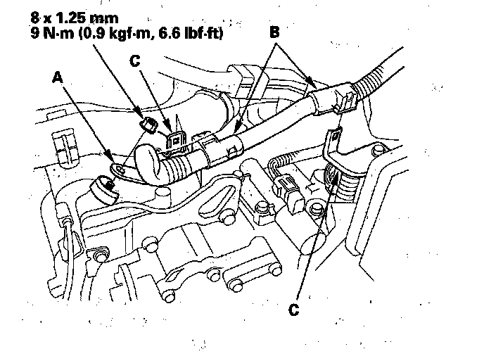
58. Refill the transmission with ATF.
59. Install the battery base.
60. Install the intake air duct and the air cleaner assembly.
61. Install the battery tray, and the battery, then secure the battery with hold-down bracket, then connect the battery cables.
62. Raise the front suspension with a floor jack to load the suspension with the vehicle's weight. Tighten the stabilizer link nuts to the specified torque value.
63. Install the splash shield and front inner fender.
64. Install the front wheels.
65. Install the engine cover.
66. Install the front grille cover.
67. Set the parking brake. Start the engine, and shift the transmission through all positions three times.
68. Check the shift lever operation, the A/T gear position indicator operation, and the shift cable adjustment.
69. Check and adjust the front wheel alignment.
70. Start the engine with the shift lever in P or N, and warm it up to normal operating temperature (the radiator fan comes on). Turn the engine off, and check the ATF level.
71. Do the road test. Initial Inspection and Diagnostic Overview
72. Enter the anti-theft code for the audio system and the navigation system (if equipped). Set the clock (on vehicles without navigation).