Part 1
Navigation System Diagnostic Mode (Part 1)
Start-up procedure and Diagnosis Menu
1. Turn the ignition switch to ON (II). Use the navigation display hard buttons as described below:
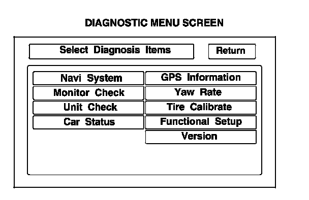
Make sure the battery is in good condition then press and hold the three buttons MENU, MAP/GUIDE, and CANCEL, for about 3 seconds. The display screen goes directly to the Select Diagnosis Items menu shown.
2. After the display changes to the Select Diagnosis Items menu, select the item you want to check and the diagnostic starts. To return to the previous screen, select RETURN.
- Navi System (Link)
- Monitor Check
- Unit Check
- Car Status
- GPS Information
- Yaw Rate
- Tire Calibrate
- Functional Setup
- Version
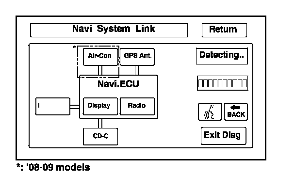
Navi System Link
- This diagnostic step tests the cables connecting the navigation components. Ensure that the ignition switch is in the ON (II) position. When the diagnosis begins, you hear a long sound. The system is in a Detecting mode, and is waiting for all items in white to be tested. This includes the voice control navigation TALK/BACK buttons, and the microphone. Press the navigation TALK button on the steering wheel, and in a normal voice, say "testing". When the system is operating properly, the TALK indicator on the screen turns green, and the voice level indicator moves to at least the 6th bar to pass. The Cancel indicator turns green.
- If all of the communication lines connecting the system components, and the navigation TALK/BACK buttons/microphone check out OK (all block diagram items are green), then the OK indicator turns green.
- If there is a problem with the system, the faulty system component item turns red, and the screen will show NG in red. Use the troubleshooting index, and other diagnostic screens to help locate the problem.
- The indicator on the screen may not change until you cycle the ignition switch. After repairing the affected cable or system, repeat this diagnostic.
NOTE: Green boxes and a green OK indicate that the communications lines (cables) are intact. This diagnostic does not necessarily imply that the individual components are functioning properly. For instance, the GPS antenna wire may be crushed, but still show as green. A road test, or other diagnostic may be necessary to find the problem.
- Select Return to return to the Diagnostic Menu, or the Exit Diag button to exit.
NOTE: The Mic Level indicator must reach the 6th bar or greater to pass the test.
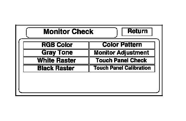
Monitor Check
Overview of navigation display
The illumination input from the gauge brightness control provides back lighting for the buttons surrounding the screen.
These screens allow you to troubleshoot the navigation display. Select the item you want to troubleshoot, and follow the diagnostic instructions.
- RGB Color
- Gray Tone
- White Raster
- Black Raster
- Color Pattern
- Monitor Adjustment
- Touch Panel Check
- Touch Panel Calibration
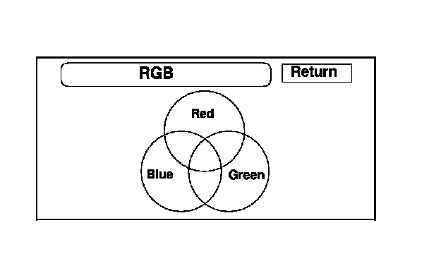
RGB Color
This screen verifies that the navigation display is receiving the video (R, G, B and Composite sync) signals properly. The three primary colors should all appear without distortion. The combination of all three should produce a central white section. If any of the colors are missing, troubleshoot for the color signal. Symptom Troubleshooting If the picture has lines in it, or scrolls horizontally or vertically, troubleshoot for a Composite sync problem. Symptom Troubleshooting
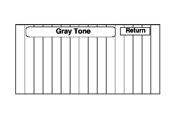
Gray Tone
This screen looks for problems with contrast. You should be able to see the changes from bar to bar across the scale. It is normal for the two bars on either side to appear the same. If you can't see changes from bar to bar, replace the navigation unit.
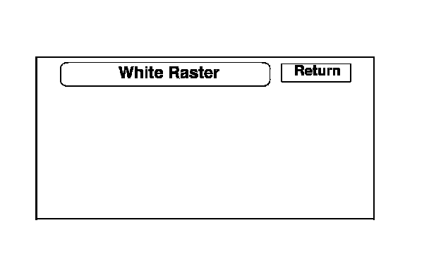
White Raster
This diagnostic screen checks for pixels that may be dead (off). The entire display must be white. If pixels are dead, replace the navigation unit.
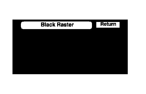
Black Raster
The entire display must be black. This diagnostic screen checks for pixels that may be stuck (on). If pixels are stuck on, replace the navigation unit.
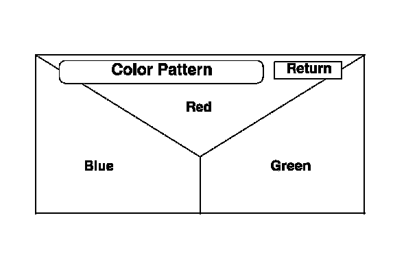
Color Pattern
The chart below shows the colors being used for the Map and Menu screens. This is for factory use only. To check the color signal use the RGB test.
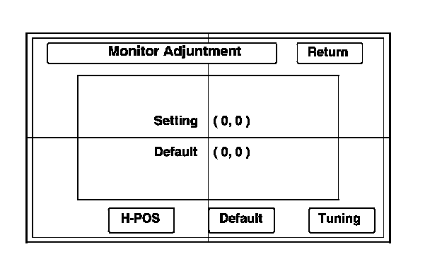
Monitor Adjustment
This allows you to center the navigation display. Use the joystick to move the picture up/down or left/right. It is unlikely that you will ever need to adjust the monitor position. The Default button will reset the display position to factory specifications. The factory default is 0, 0. The H-POS button is for factory use only.
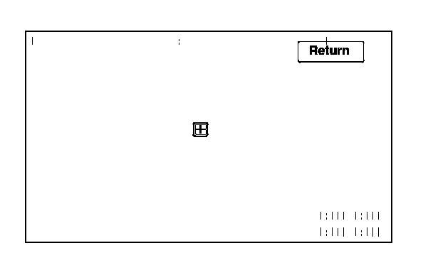
Touch Panel Check
The panel touch sensing system consists of a touch sensitive resistive membrane covering the display. Contrary to other systems using infrared beams, the screen has to be physically touched to make it work. The display has the capability of 479 locations (left to right), and 233 touch locations (top to bottom). The upper left hand corner is position (0, 0) and the lower right hand corner is (479, 233) as displayed. Touching anywhere on the screen will display the coordinate of the location, and cause the place you touch to display a + icon. If any areas of the screen either don't respond, or respond at some other location when touched, then replace the navigation unit.
NOTE: Unlike earlier screens that used infrared sensors, direct sunlight will not affect this test.
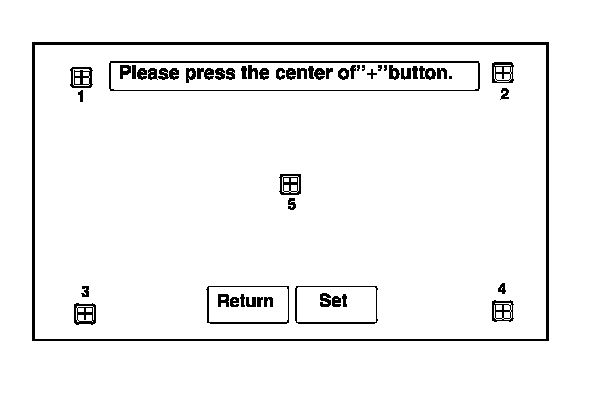
Touch Panel Calibration
The display screen uses a touch sensitive membrane. This means that every location of the entire surface of the display is touch sensitive. This diagnostic allows alignment of these touch locations with the location of the button images on the screen.
Normally this should never need adjustment, and is used only to adjust the touch locations for parallax (the touch locations appear different when viewed at an angle). However, if an adjustment is necessary, follow this procedure:
- The screen consists of the + button icons. Touch the center of the five + buttons in order 1-5.
- To store any change you make, touch the Set button.
- Use the Return key to exit the diagnostic.
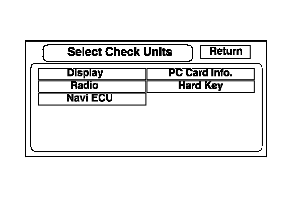
Unit Check
To start the test, select the item you want to check.
- Display
- Radio
- Navi ECU
- PC Card Info.
- Hard Key
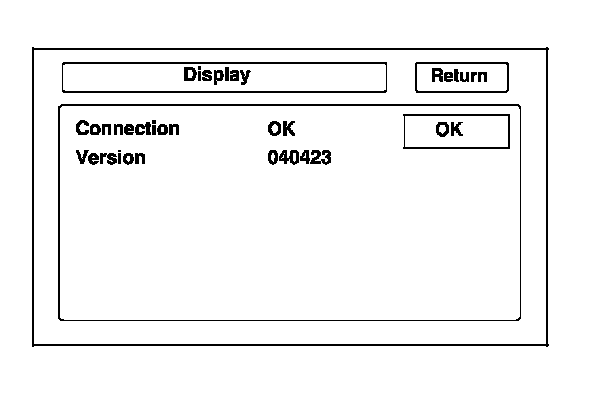
Display
This diagnostic does additional checks on the communication bus between the navi CPU and the display. In addition, this test checks the internal electronic functions.
If the connection is NG, replace the navigation unit.
- Connection verifies internal communications.
- Version represents the software version for the display.
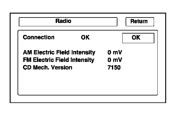
Radio
This diagnostic screen checks the internals of the radio (AM and FM) and CD player. If NG, replace the navigation unit.
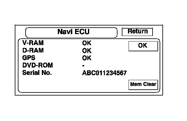
Navi ECU
This screen looks for problems with the navigation unit. When you initiate this diagnostic, the navigation unit may freeze or delay up to a minute while the diagnostic runs.
- If V-RAM or D-RAM is NG, then replace the navigation unit.
- If GPS indicates NG (ANT), then check the entire GPS antenna wire from the navigation unit to the antenna. If the wire is crushed or damaged, try a known-good antenna. If this diagnostic reads OK, then order a new GPS antenna. If the diagnostic still reads NG (ANT), then replace the navigation unit.
- DVD ROM represents the database version on the DVD. You can also find this information in Setup by selecting System Information.
- Serial No. should be the same as the serial number found on the underside of the navigation unit. You need this number to obtain the security code from the Interactive Network (iN) system.
- Mem Clear is for factory use, and should never be used unless instructed by the factory. Accidental selection will erase the customer's personal data, PINS, and settings. If selected, a popup box appears asking if you want to clear the memory. If so, select Yes.
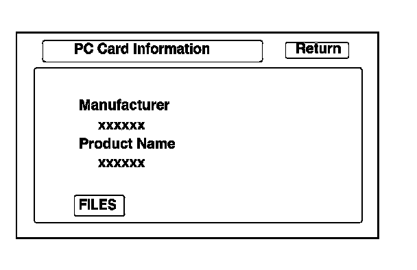
PC Card Info.
There is no PC Card in the PC slot, and the screen should display, "PC Card is not inserted".
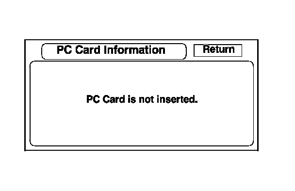
If the factory provides a PC card and instructs you to insert it, the screen displays the Manufacturer, and Product Name as shown in the following screen. Follow the instructions provided by the factory to complete the test.
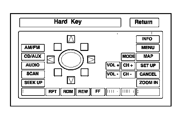
Hard Key
This diagnostic screen checks the status of each of the hard buttons surrounding the navigation display. When you press each hard button, the corresponding item on the screen should flash blue. Touch the return key, or press and hold the joystick to exit.
NOTE: VOL/PWR knob operation (turn, push) and OPEN/CLOSE button operation are not displayed.
Car Status
Use this screen to confirm that the navigation unit is properly receiving input signals. Signals equal to (0) are OFF, and signals equal to (1) are ON. If the value on the display does not match the actual vehicle status, then check the wire carrying the signal.
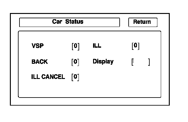
- VSP-Vehicle Speed Pulse from PCM connector A (Terminal 13 of navigation unit connector A, 17P)
a) OFF (0) when vehicle is not moving
b) ON (1) when vehicle is moving
The VSP comes from the PCM as a dedicated signal. Internally, the navigation unit compares the actual VP on the map against street data to adjust the pulse to speed scaling factor.
- BACK-Reverse indication from taillight relay (Terminal 7 of navigation unit connector C, 12P)
a) OFF (0) when shift lever is in any position other than reverse
b) ON (1) when shift lever is in reverse
The Back signal is used by the navigation unit to allow the map screen to show the VP moving backwards when in reverse and to trigger the optional rearview camera. This signal is needed because the Speed Pulse does not provide any directional information to the system.
- ILL CANCEL
a) OFF (0) when the gauge assembly brightness control is less than 90 % brightness with the headlights on.
b) ON (1) when the gauge assembly brightness knob is more than 90 % brightness with the headlights on.
- ILL-Illumination Indication (Terminal 10 of navigation unit connector A, 17P)
a) OFF (0) when parking lights or headlights are off
b) ON (1) when parking lights or headlights are on
This signal is used by the navigation unit to determine whether to put the navigation screen into the Day or Night brightness mode. (Setup screen 1)
- The Display function displays the position of the display.
a) (Close) when the display is closed
b) (Open) when the display is open
The navigation unit has a microswitch to detect this. If open is indicated when the display is closed, replace the navigation unit.
(Continued in Part 2)