A/T System Description - Electronic Control System
A/T System Description - Electronic Control System
Electronic Control System
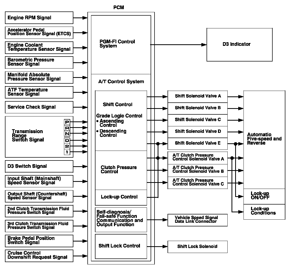
Functional Diagram
The electronic control system consists of the powertrain control module (PCM), the sensors, and the solenoid valves.
Shifting and lock-up are electronically controlled for comfortable driving under all conditions.
The PCM receives input signals from the sensors, switches, and other control units, processes data, and outputs signals for the engine control system and the A/T control system. The A/T control system includes shift control, grade logic control, clutch pressure control, and lock-up control.
The PCM actuates the shift solenoid valves and the A/T clutch pressure control solenoid valves ON and OFF to control shifting the transmission gears and the torque converter lock-up.
Shift Control
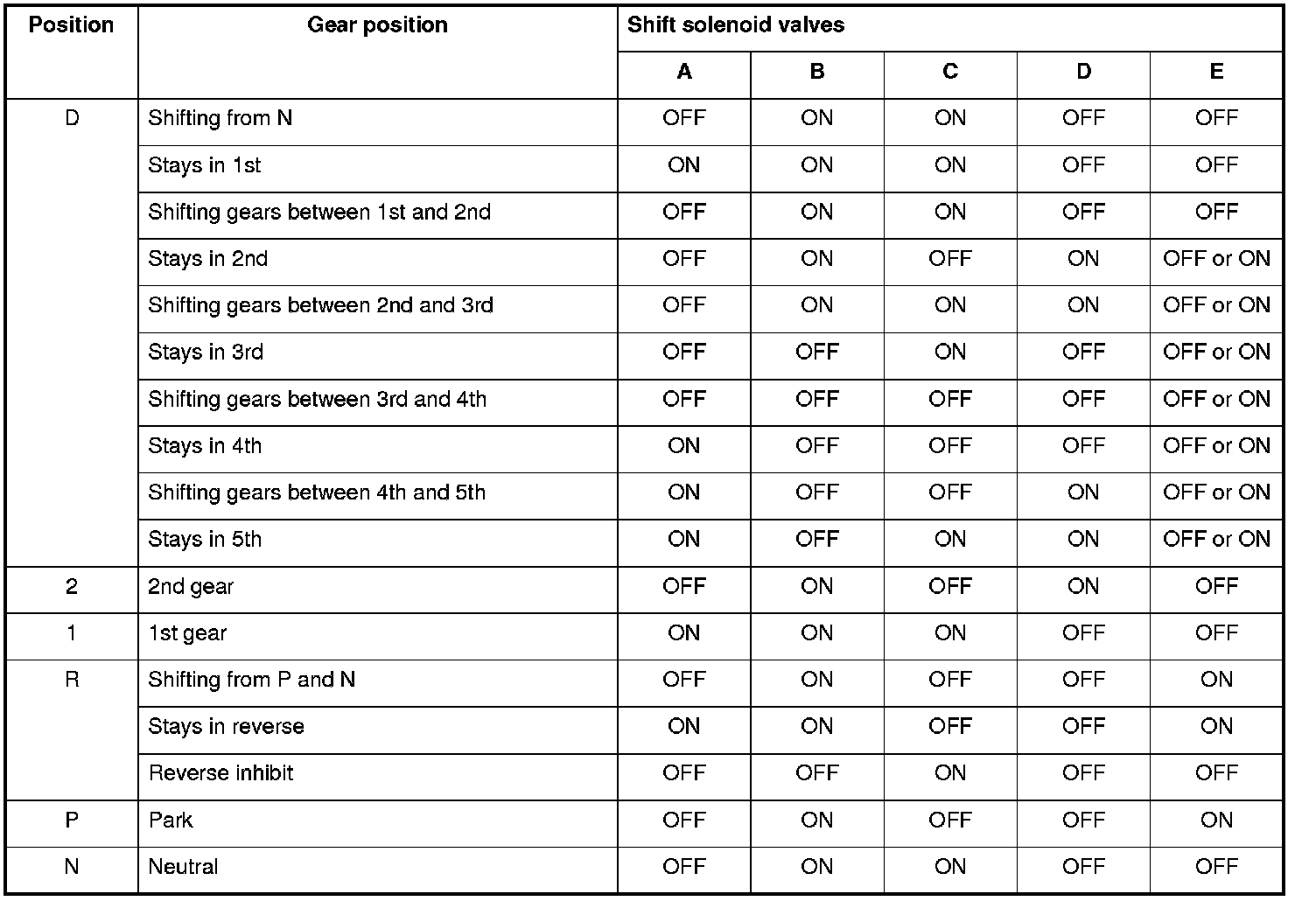
The PCM instantly determines which gear should be selected by various signals sent from the sensors and the switches, and it actuates shift solenoid valves A, B, C, D, and E to control gear selection.
The shift solenoid valves are a normally closed type valves. The shift solenoid valve opens the port of the shift solenoid valve pressure leading to the shift valves, while the shift solenoid valve is turned ON by the PCM, and closes the port when the shift solenoid valve is OFF.
The combination of driving signals to shift solenoid valves A, B, C, D, and E are shown in the table.
Electronic Control System (cont'd)
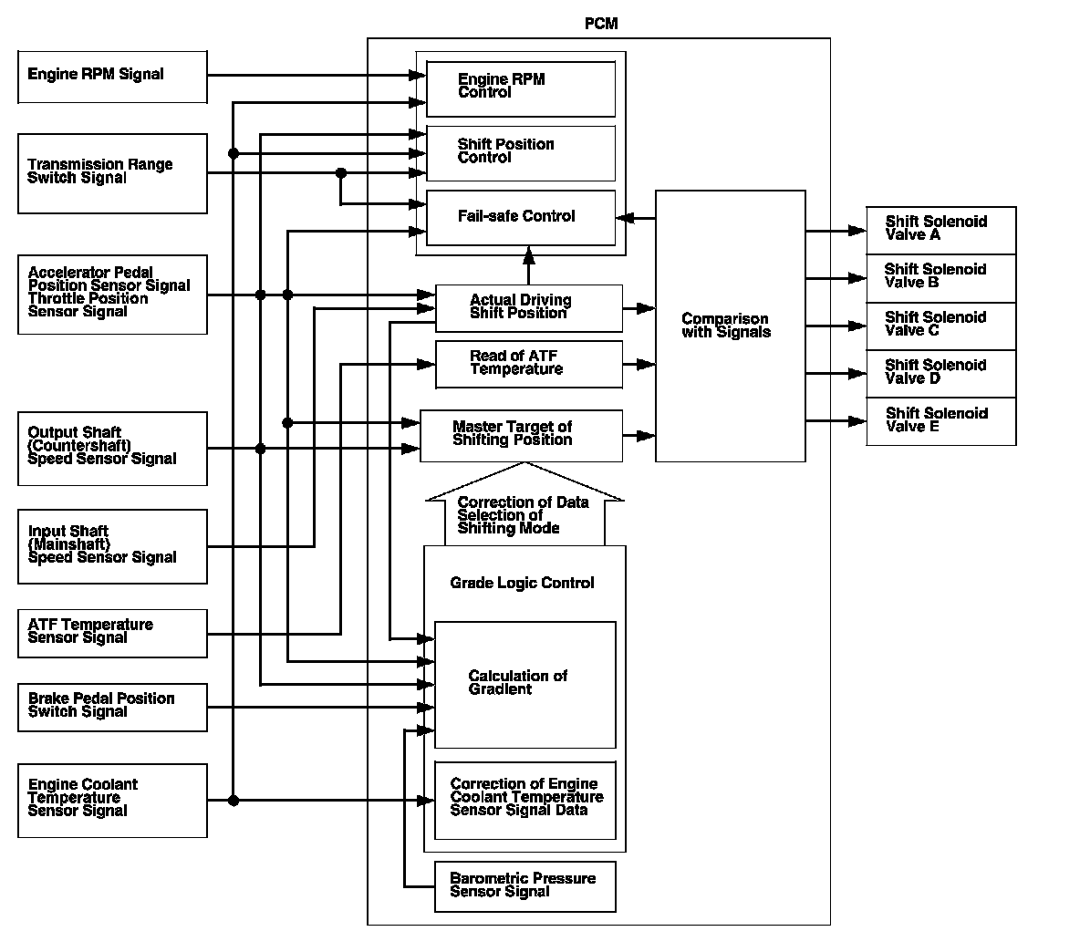
Shift Control - Grade Logic Control
The grade logic control system has been adopted to control shifting in D. The PCM compares actual driving conditions with programmed driving conditions, based on signals from the accelerator pedal position sensor, the throttle position sensor, the engine coolant temperature sensor, the barometric pressure sensor, the brake pedal position switch signal, and the shift lever position signal, to control shifting while the vehicle is ascending or descending a slope.
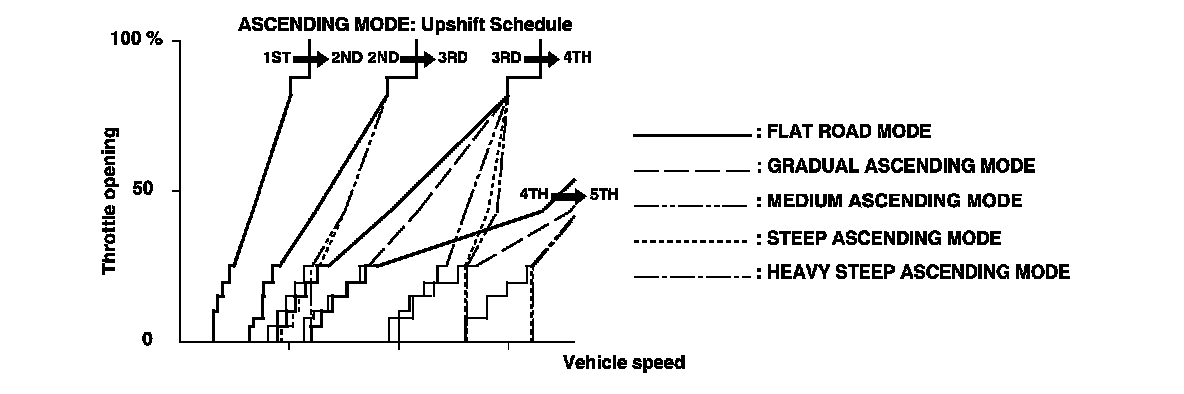
Grade Logic Control: Ascending Control
When the PCM determines that the vehicle is climbing a hill in D, the grade logic system extends the engagement area of 2nd, 3rd, and 4th gears to prevent the transmission from frequently shifting between 2nd and 3rd gears, between 3rd and 4th gears, and between 4th and 5th gears, so the vehicle can run smoothly, and have more power when needed.
Shift programs stored in the PCM between 2nd and 3rd gears, between 3rd and 4th gears, and between 4th and 5th gears, enable it to automatically select the most suitable gear according to the magnitude of a gradient.
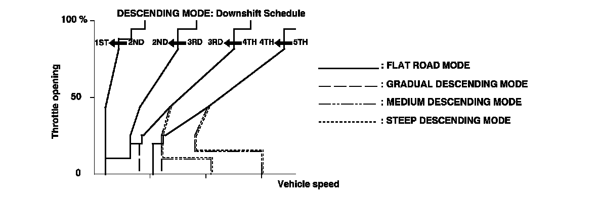
Grade Logic Control: Descending Control
When the PCM determines that the vehicle is going down a hill in D, the upshift speed from 4th to 5th gear, from 3rd to 4th gear, and from 2nd to 3rd gear (when the throttle is closed) becomes higher than the set speed for flat road driving to extend 4th gear, 3rd gear, and 2nd gear driving area. This, in combination with engine braking from the deceleration lock-up, achieves smooth driving when the vehicle is descending. There are three descending modes with different 4th gear driving areas, 3rd gear driving areas, and 2nd gear driving areas according to the magnitude of a gradient stored in the PCM. When the vehicle is in 5th gear or 4th gear, and you are decelerating when you are applying the brakes on a steep hill, the transmission downshifts to lower gear. When you accelerate, the transmission then returns to a higher gear.
Electronic Control System (cont'd)
Shift Control - D Position D3 Driving Mode Control
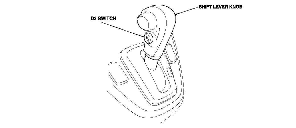
The automatic transmission is provided with the D3 driving mode in D. D has two modes; general driving mode (shifts gears automatically 1st through 5th), and the D3 driving mode (shifts gears automatically 1st through 3rd). The transmission mode switches by pushing the D3 switch on the shift lever knob in D.
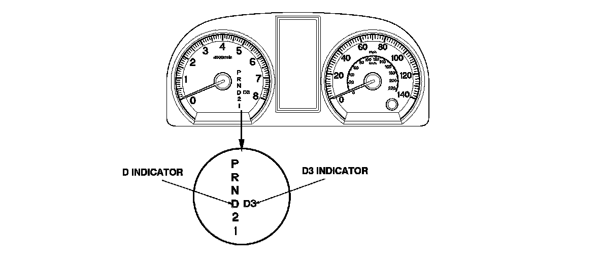
In the D3 driving mode, the D3 indicator next to the D indicator in the gauge assembly comes on. The D3 driving mode is cancelled by pushing the D3 switch, and the D3 indicator goes off. Also, the D3 driving mode is cancelled when the ignition switch is turned to LOCK (0). When the shift lever is moved out of D in the D3 driving mode, the D3 indicator goes off, but when returning the shift lever to D, the transmission returns to the D3 driving mode, and the D3 indicator comes on.
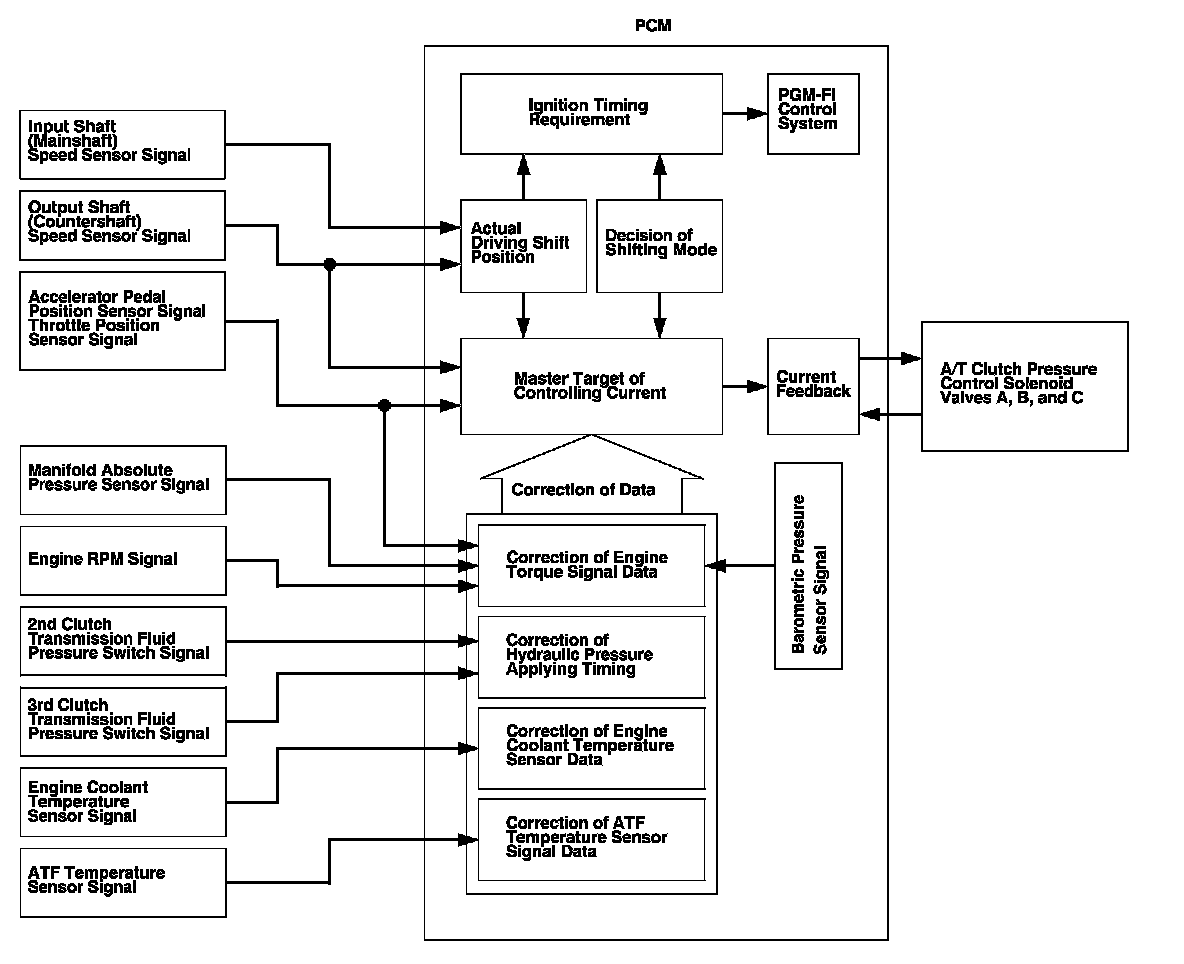
Clutch Pressure Control
The PCM actuates A/T clutch pressure control solenoid valves A, B, and C to control the clutch pressure. When shifting between the lower and higher gears, the clutch pressure regulated by A/T clutch pressure control solenoid valves A, B, and C engages and disengages the clutch smoothly.
The PCM receives input signals from the various sensors, switches, processes the data, and outputs current to A/T clutch pressure control solenoid valves A, B, and C.
Electronic Control System (cont'd)
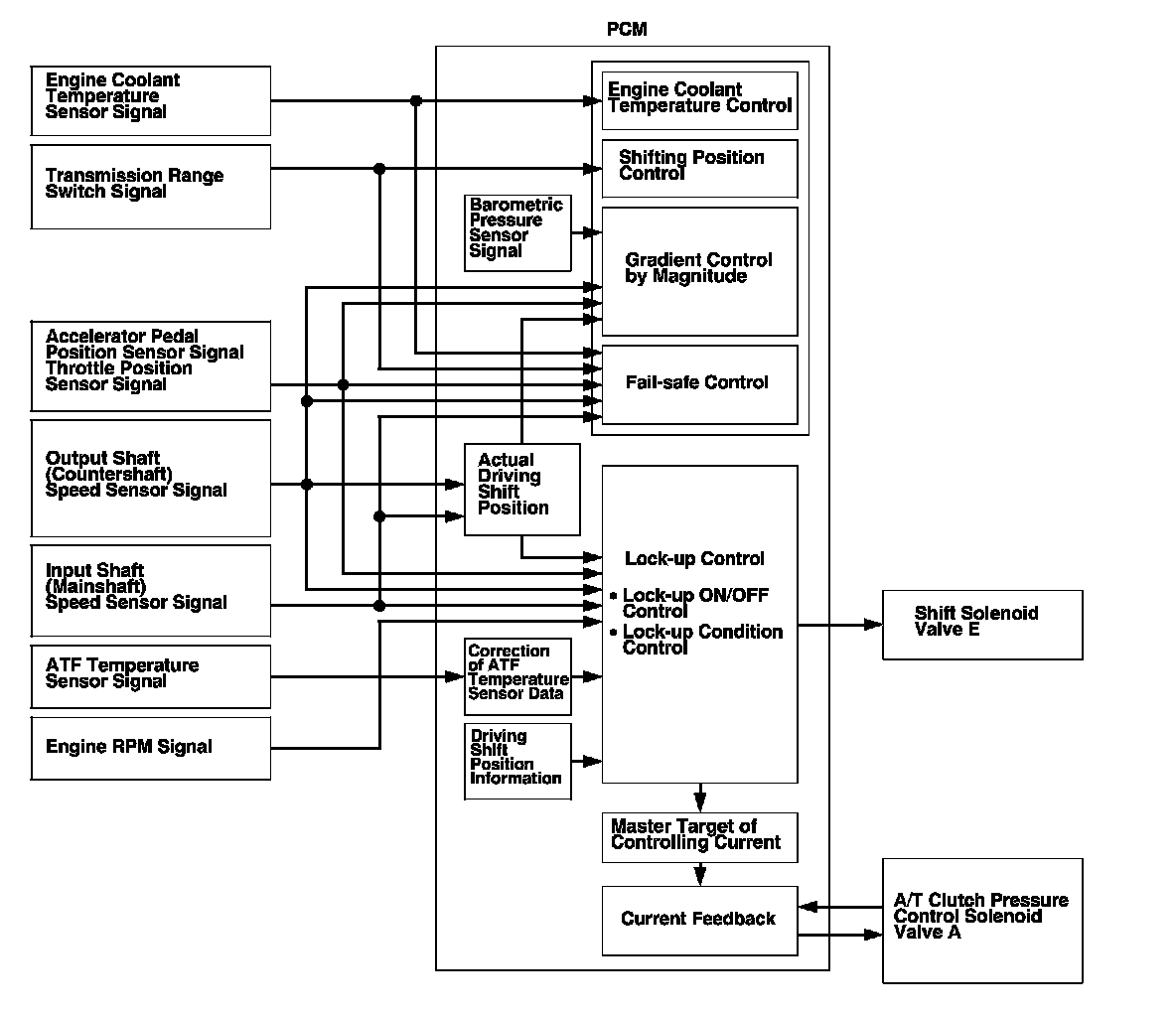
Lock-up Control
Shift solenoid valve E controls the hydraulic pressure to switch the lock-up shift valve ON and OFF. The PCM turns shift solenoid valve E and A/T clutch pressure control solenoid valve A ON, and lock-up starts. A/T clutch pressure control solenoid valve A regulates and applies hydraulic pressure to the lock-up control valve to control the volume of the lock-up.
The lock-up mechanism operates in D (2nd, 3rd, 4th, and 5th), and in D in the D3 driving mode (2nd and 3rd).
Self-diagnosis
If the PCM detects the failure of a signal from a sensor, a switch, a solenoid valve, or from another control unit, it stores a Temporary DTC or a DTC. Depending on the failure, a DTC is stored in either the first or the second drive cycle. When a DTC is stored, the PCM blinks the D indicator and/or turns on the malfunction indicator lamp (MIL) by a signal sent to the gauge control module via F-CAN.
- One Drive Cycle Detection Method
When an abnormality occurs in the signal from a sensor, a switch, a solenoid valve, or from another control unit, the PCM stores a DTC for the failure and blinks the D indicator and/or turns on the MIL immediately.
- Two Drive Cycle Detection Method
When an abnormality occurs in the signal from a sensor, a switch, a solenoid valve, or from another control unit in the first drive cycle, the PCM stores a Temporary DTC. The D indicator and the MIL do not turns on at this time. If the failure continues in the second drive cycle, the PCM stores a DTC and blinks the D indicator and/or turns on the MIL.
Fail-safe Function
When an abnormality occurs in the signal from a sensor, a switch, a solenoid valve, or from another control unit, the PCM ignores that signal and substitutes a pre-programmed value for them that allow the automatic transmission to continue driving. This causes a DTC to be stored and the D indicator to blink and/or the MIL to come on.
Electronic Control System (cont'd)
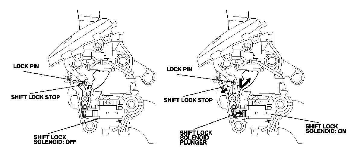
Shift Lock Control
The shift lock control system reduces the risk of unintentional engine starting. Starting the engine is possible only in P and N, and the shift lever cannot be shifted out of P without pressing the brake pedal and releasing the accelerator. The shift lock mechanism consists of the shift lock solenoid, shift lock stop, shift lock release, and related parts. The shift lock solenoid is electronically controlled by the shift lock control system signals.
In P without pressing the brake pedal or while pressing the accelerator, the shift lock solenoid keeps OFF, and the shift lever cannot be shifted out of P because the shift lock stop stops the lock pin. However while the brake pedal is pressed and the accelerator is released, the shift lock solenoid is turned ON, and the shift lock solenoid plunger is retracted, releasing the shift lock stop. Pushing the shift lever button passes the lock pin through the shift lock stop, and allows the shift lever to be shifted out of P.
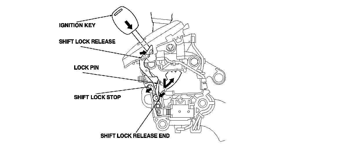
When a shift lock control system malfunction or a mechanical problem occurs, the shift lever can be shifted out of P temporarily by pressing the shift lock release with the ignition key and screwdrivers. Pushing the shift lock release releases the shift lock stop, and allows the shift lever to be shifted out of P.
PCM A/T Control System Electrical Connections
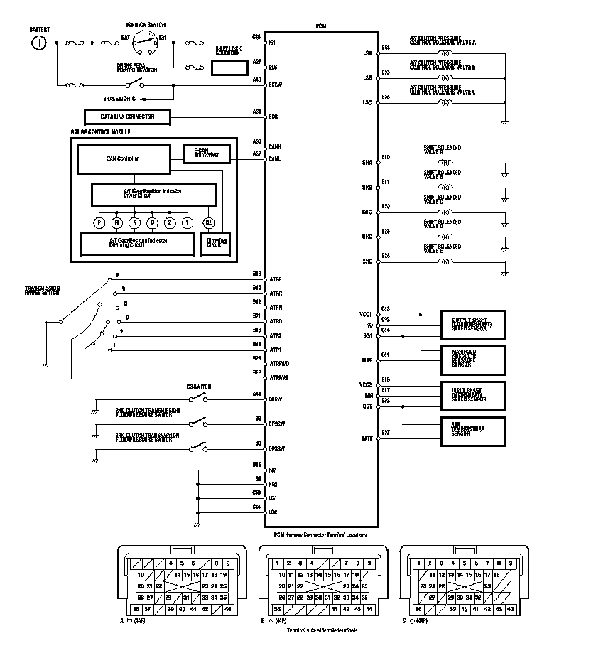
Electronic Control System (cont'd)
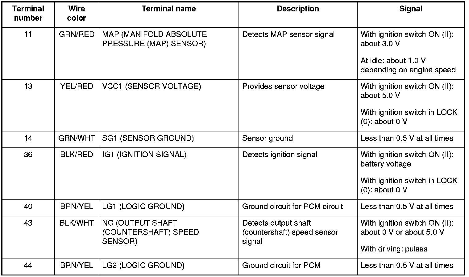
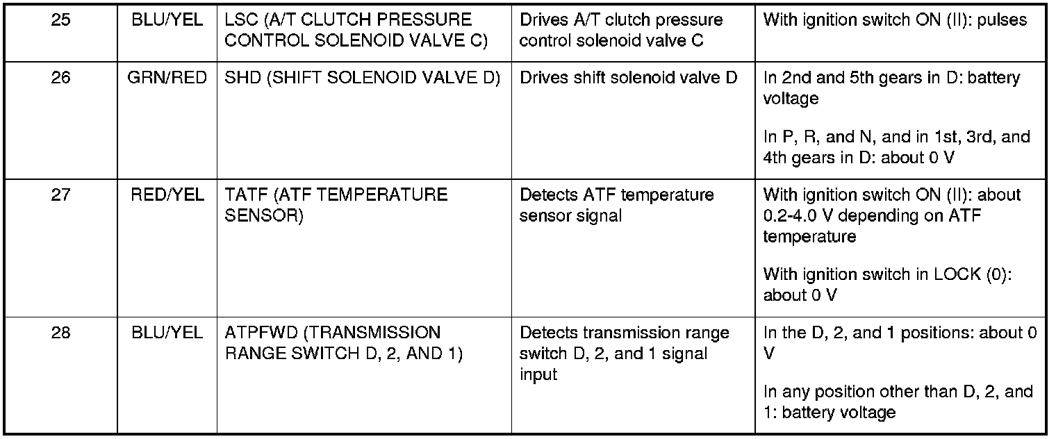
PCM A/T Control System Inputs and Outputs

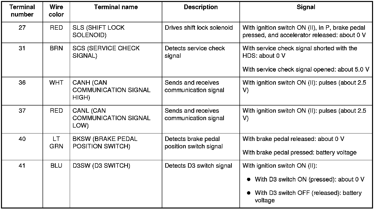
PCM CONNECTOR A (square) (44P)
PCM CONNECTOR B (triangle) (44P)
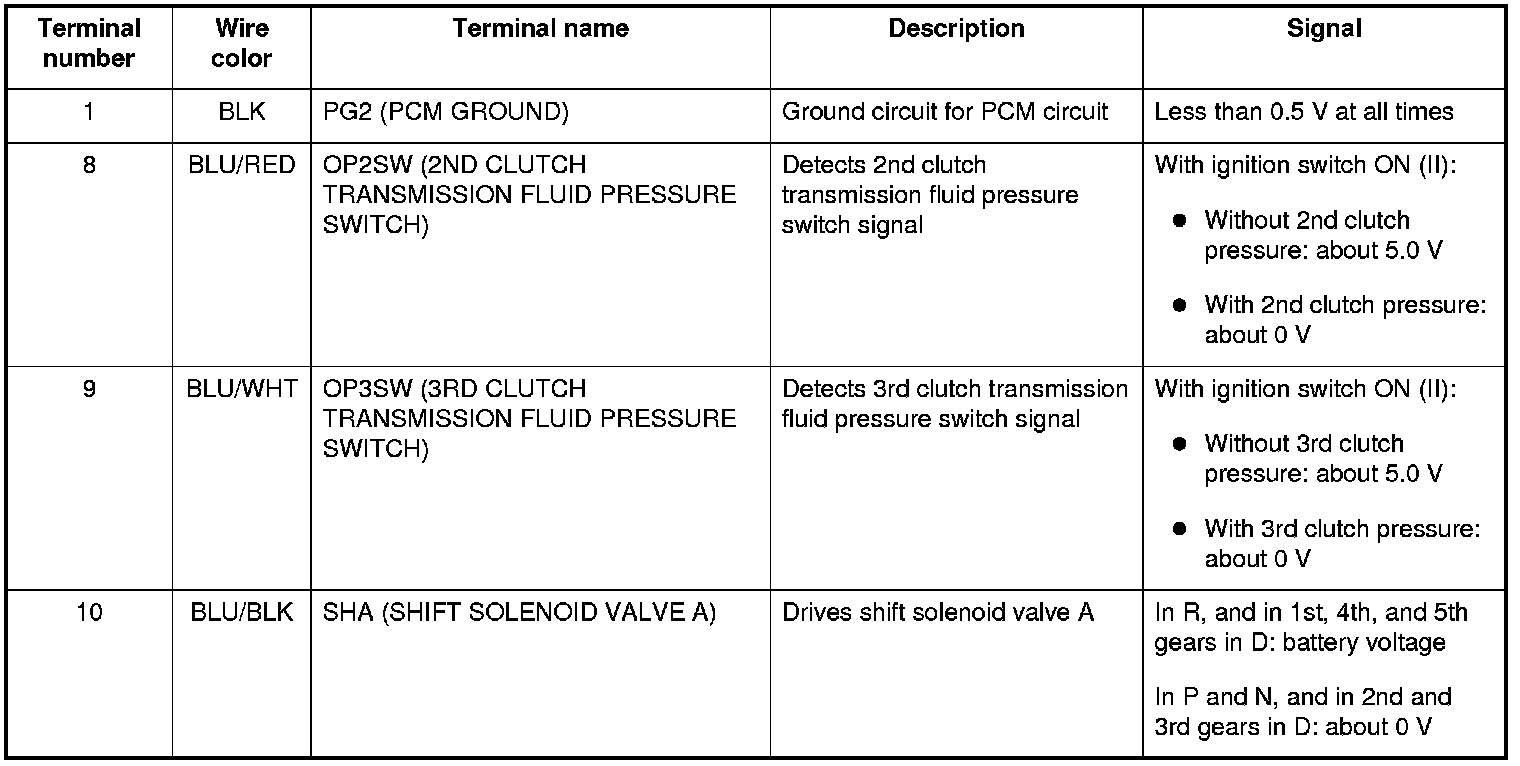
PCM CONNECTOR B (triangle) (44P)
Electronic Control System (cont'd)
PCM A/T Control System Inputs and Outputs (cont'd)
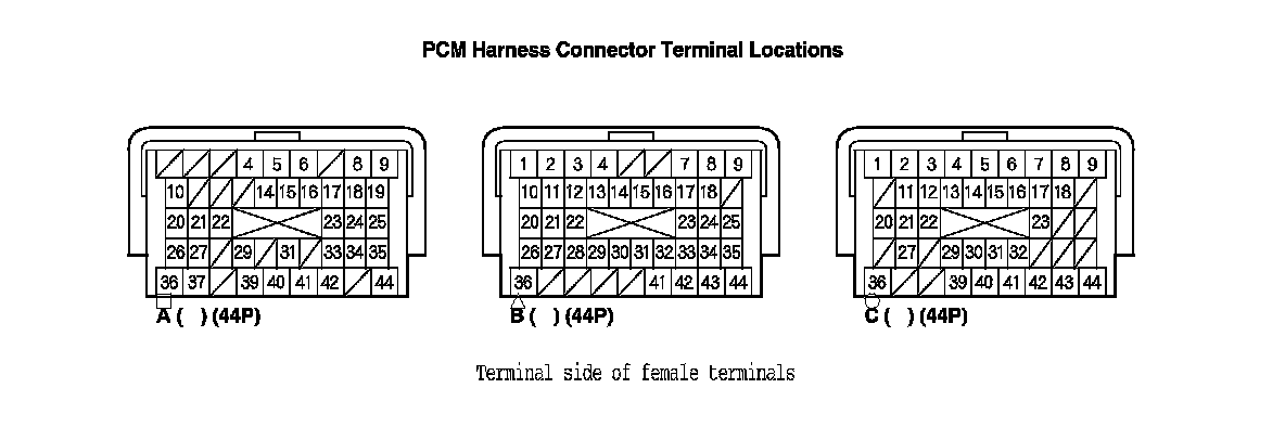
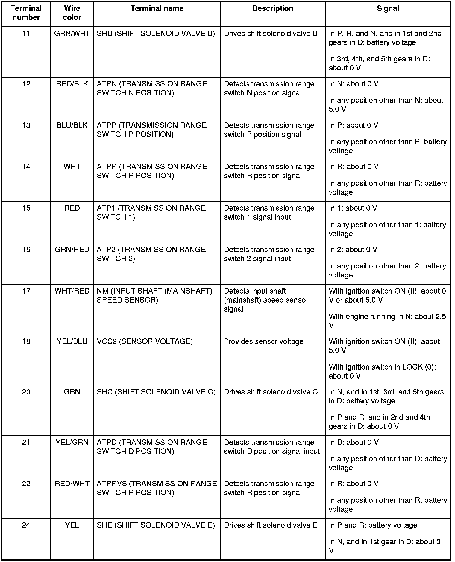
PCM CONNECTOR B (triangle) (44P)
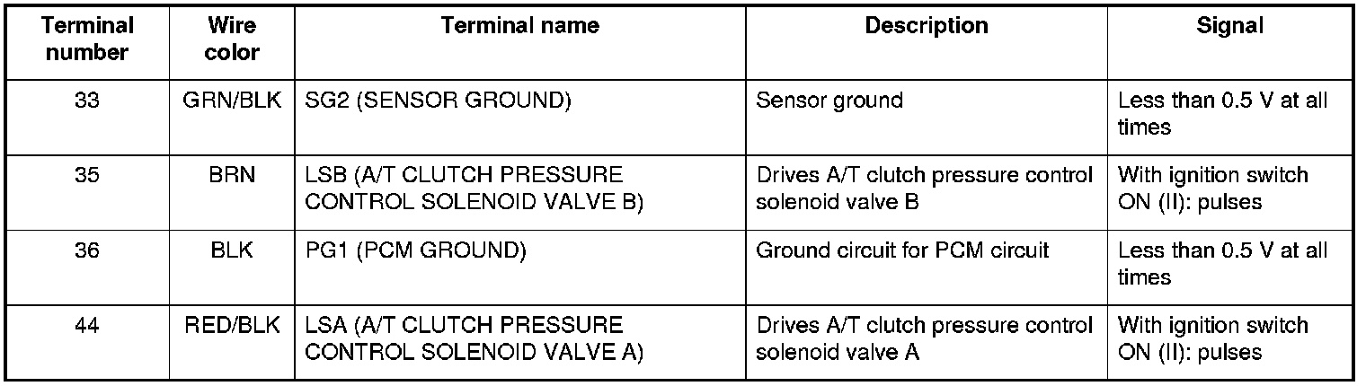
PCM CONNECTOR C (circle) (44P)