Part 1
Service Information
Cylinder Bore Honing
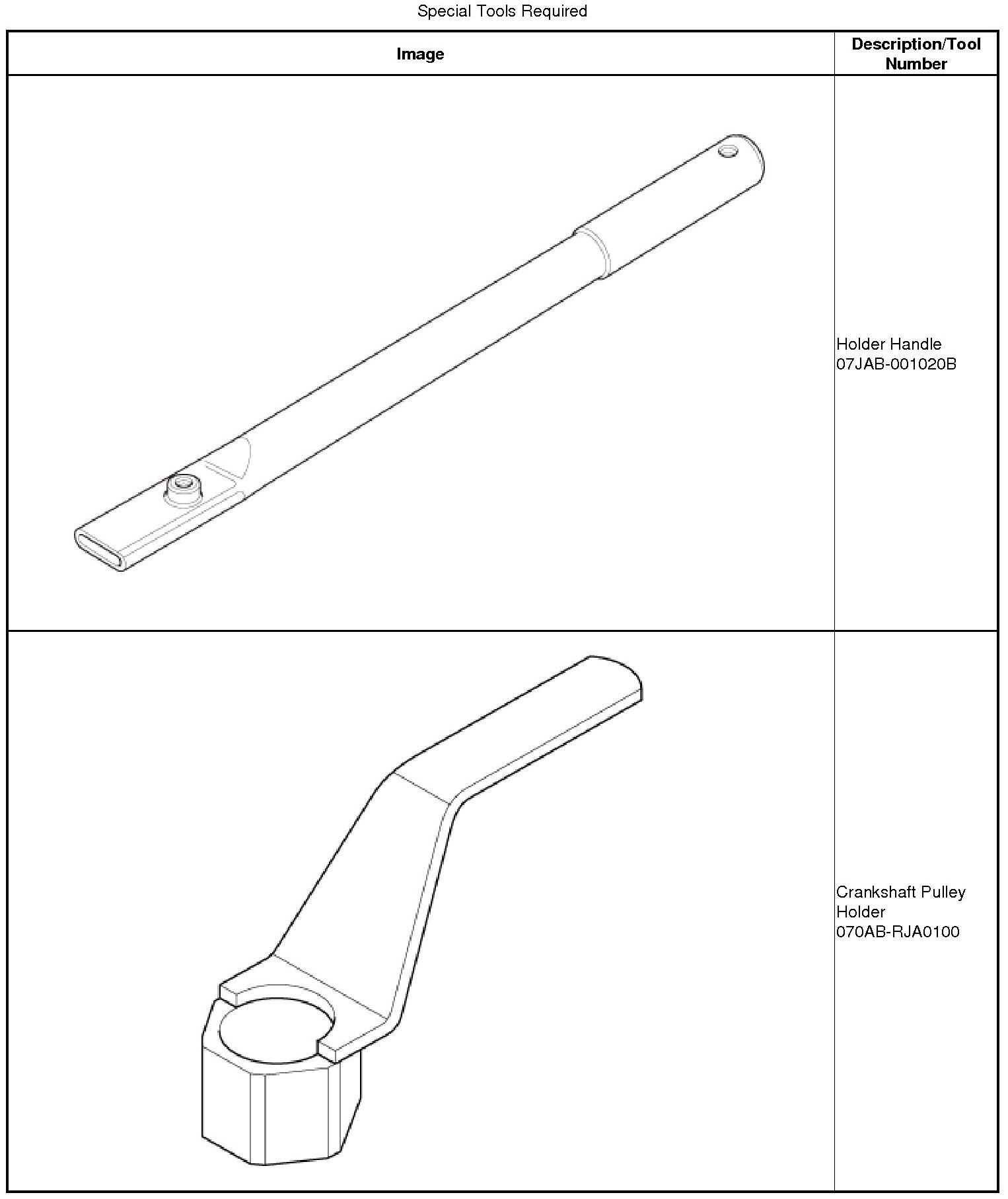
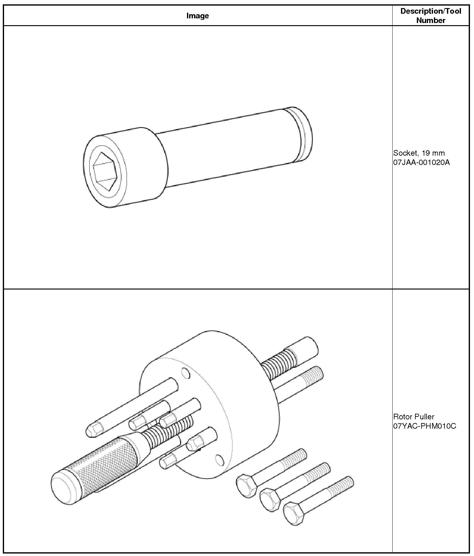
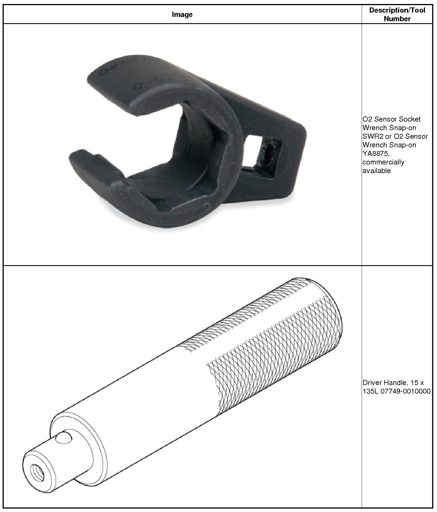
Removal
1. Engine Wire Harness
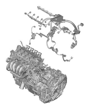
1. Remove the engine wire harness.
2. Starter
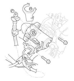
1. Remove the starter.
3. CVT Transmission Assembly
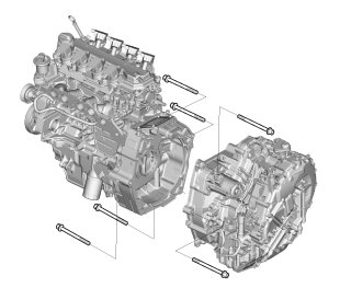
1. Remove the CVT transmission assembly.
4. CVT Flywheel
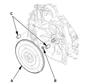
1. Remove the flywheel (A) and the sealing ring (B) from the input shaft, then remove the dowel pins (C).
5. Drive Plate Assembly
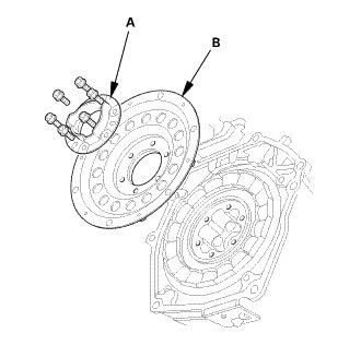
1. Remove the flywheel support (A) and the drive plate (B).
2. Inspect the drive plate and the flywheel support, and replace it if it is damaged.
6. IMA Motor Rotor
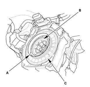
1. Tape together end to end two plastic sheets (300 long by 200 wide by 0.2 mm thick) and install them between the IMA motor rotor (B) and motor stator (C) to protect them during removal.
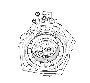
2. Remove three of the six bolts as shown.
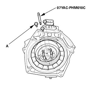
3. Install the rotor puller guide pins, then remove the remaining three bolts (A).
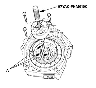
4. Attach the rotor puller with it's supplied bolts.
NOTE: When installing the rotor puller, position the puller to fit over the guide pins (A).
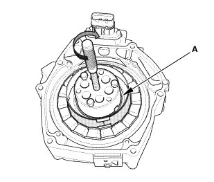
5. Turn the handle of rotor puller.
6. Remove the IMA motor rotor (A).
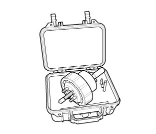
7. To prevent damage to the rotor magnet while working on the stator, place the rotor with the puller attached into the puller case.
7. IMA Motor Housing
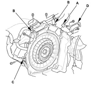
1. Remove the connector (A), the stays (B), the harness clamp (C), and the heat shield (D).
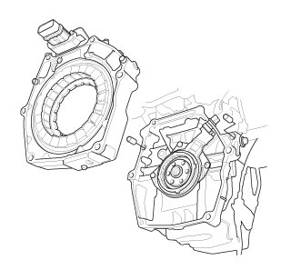
2. Remove the IMA motor housing.
8. IMA Motor Rotor Position Sensor
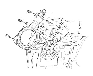
1. Remove the IMA motor rotor position sensor.
9. Intake Manifold Bracket
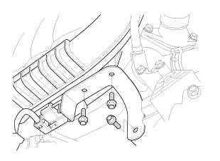
1. Remove the intake manifold bracket.
10. Intake Manifold/Chamber and Throttle Body Assembly
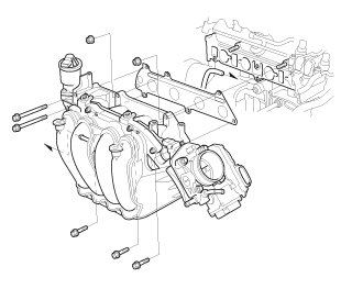
1. Remove the intake manifold/chamber assembly with the throttle body.
11. A/F Sensor
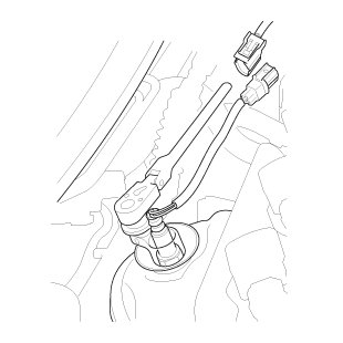
1. Remove the A/F sensor.
12. Exhaust Chamber Cover
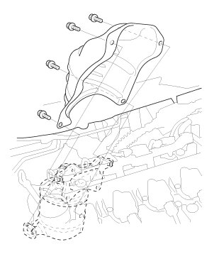
1. Remove the exhaust chamber cover.
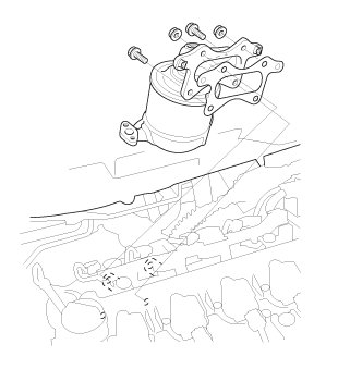
13. WU-TWC and EGR Pipe Assembly
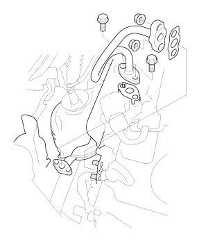
1. Remove the EGR pipe.
2. Remove the warm up TWC assembly.
14. Water Pump Pulley
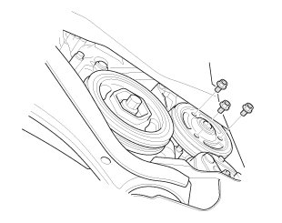
1. Remove the water pump pulley.
15. Auto Tensioner Assembly
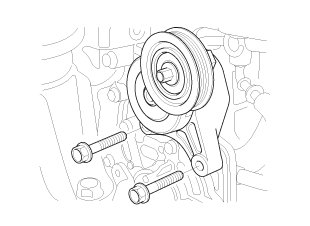
1. Remove the drive belt auto-tensioner.
16. Water Pump
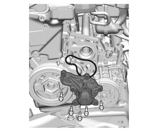
1. Remove the water pump.
17. Thermostat Housing Assembly
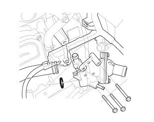
1. Remove the thermostat housing assembly.
18. Ignition Coil
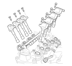
1. Remove the ignition coil.
19. Cylinder Head Cover and/or Packing
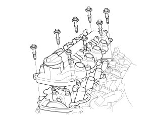
1. Remove the cylinder head cover.
20. Check the No.1 Piston at Top Dead Center (With Cam Chain Case/Oil Pump)
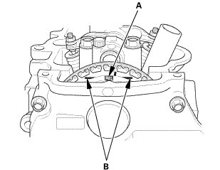
1. Set the No. 1 piston at top dead center (TDC). The "UP" mark (A) on the camshaft sprocket should be at the top, and the TDC grooves (B) on the camshaft sprocket should line up with the top edge of the head.
21. Crankshaft Pulley
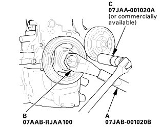
1. Hold the pulley with the holder handle (A) and the crankshaft pulley holder (B).
2. Remove the bolt with a socket, 19 mm (C) and a breaker bar.
3. Remove the crankshaft pulley.
22. Cam Chain Case
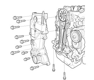
1. Remove the cam chain case.
23. Cam Chain Tensioner Slider
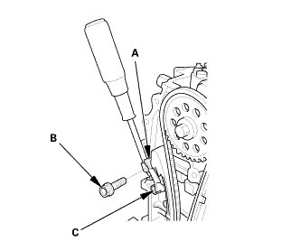
1. Apply new engine oil to the sliding surface of the cam chain tensioner slider (A).
2. Hold the cam chain tensioner slider with a screwdriver, then remove the upper bolt (B), and loosen the lower bolt (C).
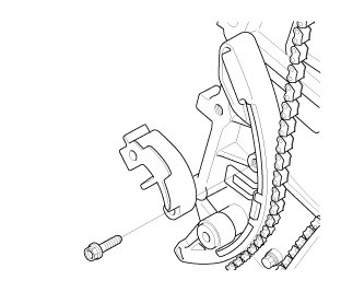
3. Remove the cam chain tensioner slider.
24. Cam Chain Tensioner and Guide
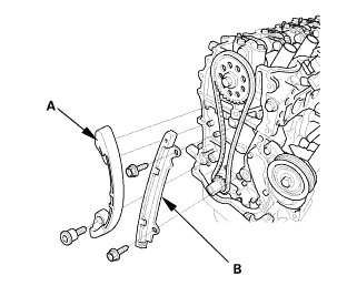
1. Remove the cam chain tensioner (A) and the cam chain guide (B).
25. Cam Chain
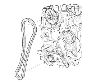
1. Remove the cam chain.
26. Cylinder Head Assembly
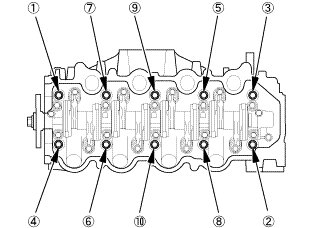
1. Remove the cylinder head bolts. To prevent warpage, loosen the bolts in sequence, 1/3 turn at a time, repeat the sequence until all bolts are loosened.
2. Remove the cylinder head.
27. Oil Pan Assembly
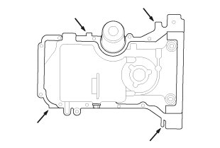
1. Remove the bolts securing the oil pan.
2. a flat blade screwdriver where shown, and separate the oil pan from the engine block.
3. Remove the oil pan.
NOTE: Lower the oil pan carefully not to damage the IMA motor (resolver stator).
28. Engine Oil Strainer
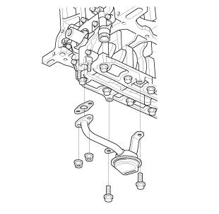
1. Remove the oil strainer.
29. Engine Oil Pump Assembly
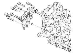
1. Remove the oil pump.
30. Crankshaft Oil Seal Transmission Side
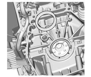
1. Remove the crankshaft oil seal.
31. Crankshaft Bearing Caps/Bearing Halves
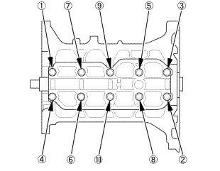
1. Remove the bearing cap bridge bolts. To prevent warpage, loosen the bolts in sequence 1/3 turn at a time; repeat the sequence until all bolts are loosened.
2. Remove the bearing cap bridge.
3. Remove the connecting rod caps/bearings. Keep all caps/bearings in order.
32. Connecting Rod Caps/Bearing Halves
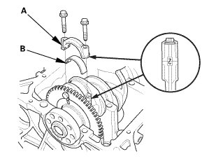
1. Remove the connecting rod caps (A) and the connecting rod bearing halves (B). Keep all connecting rod caps/bearing halves in order.
33. Crankshaft Assembly
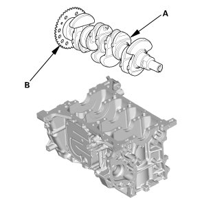
1. Lift crankshaft (A) out of the engine block, being careful not to damage the journals and the CKP pulse plate (B).
34. Piston/Connecting Rod Assembly
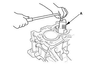
1. If you can feel a ridge of metal or hard carbon around the top of each cylinder, remove it with a ridge reamer (A). Follow the reamer manufacturer's instructions. If the ridge is not removed, it may damage the piston as it is pushed out.
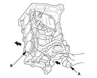
2. Use the wooden handle of a hammer (A) to drive out the piston/connecting rod assembly (B). Take care not to damage the oil jets or cylinder with the connecting rod.
3. Reinstall the connecting rod bearings and caps after removing each piston/connecting rod assembly.
4. Mark each piston/connecting rod assembly with its cylinder number to make sure they are reinstalled in the original order.
NOTE: The existing number on the connecting rod does not indicate its position in the engine, it indicates the rod bore size.
Honing
1. Cylinder Bore Honing

1. Hone the cylinder bores with honing oil and a fine (400 grit) stone in a 60 degree cross-hatch pattern (A).
NOTE:
* Use only a rigid hone with 400 grit or finer stone such as Sunnen, Ammco, or equivalent.
* Do not use stones that are worn or broken.
2. When honing is complete, thoroughly clean the engine block of all metal particles. Wash the cylinder bores with hot soapy water, then dry and oil them immediately to prevent rusting.
NOTE: Never use solvent, it will only redistribute the grit on the cylinder walls.
3. If scoring or scratches are still present in the cylinder bores after to the service limit, rebore the engine block. Some light vertical scoring and scratching is acceptable if it is not deep enough to catch your fingernail, and does not run the full length of the bore.
Installation
1. Piston/Connecting Rod Assembly
1. Remove the connecting rod caps, then check that the bearing is securely in place.
2. Apply new engine oil to the piston, inside of the ring compressor, and the cylinder bore, then attach the ring compressor to the piston/connecting rod assembly.
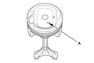
3. Position the mark (A) to face the cam chain side of the engine block.
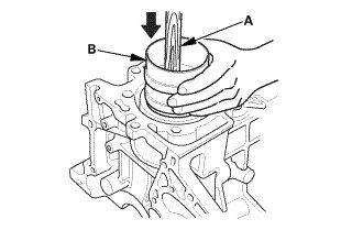
4. Position the piston/connecting rod assembly in the cylinder, and tap it in using the wooden handle of a hammer (A). Push down on the ring compressor (B) to prevent the rings from expanding before entering the cylinder bore.
5. Stop after the ring compressor pops free, and check the connecting rod-to-rod journal alignment before pushing the piston into place.
2. Crankshaft Assembly
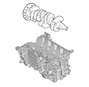
1. Hold the crankshaft so rod journal No. 2 and rod journal No. 3 are straight up, and lower the crankshaft into the engine block.
3. Main Bearing Clearance - Inspection
1. Clean each main journal and bearing half with a clean shop towel.
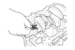
2. Place one strip of plastigage across each main journal.
3. Reinstall the bearings and the lower block, then torque the bolts to 25 Nm (2.5 kgfm, 18 lbft) +40 ° in the proper sequence.
NOTE:
* Apply new engine oil to the bolt threads and flanges.
* Do not rotate the crankshaft during inspection.
4. Remove the lower block and the bearings again, and measure the widest part of the plastigage.

5. If the plastigage measures too wide or too narrow, remove the crankshaft, and remove the upper half of the bearing. Install a new, complete bearing with the appropriate color code(s), and recheck the clearance. Do not file, shim, or scrape the bearings or the caps to adjust clearance.
6. If the plastigage shows the clearance is still incorrect, try the next larger or smaller bearing (the color listed above or below the current one), and check again. If the proper clearance cannot be obtained by using the appropriate larger or smaller bearings, replace the crankshaft, and start over.
4. Crankshaft Bearing Selection
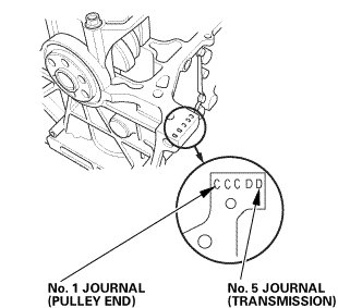
1. Numbers, letters, or bars have been stamped on the end of the engine block as a code for the size of each of the five main journal bores. Write down the crank bore codes. If you cannot read the codes because of accumulated dirt and dust, do not scrub them with a wire brush or scraper. Clean them only with solvent or detergent.
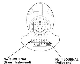
2. The main journal codes are stamped on the crankshaft.
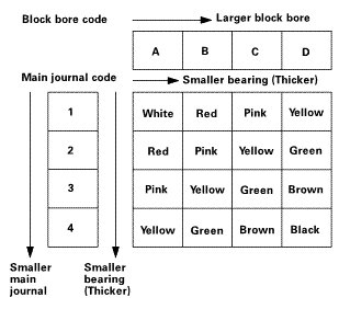
3. Use the block bore codes and the main journal codes to select the appropriate replacement bearings from the following table.
NOTE:
* Color code is on the edge of the bearing.
* When using bearing halves of different colors, it does not matter which color is used in the top or bottom.
5. Connecting Rod Bearing Clearance - Inspection
1. Place plastigage across the rod journal.
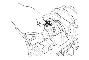
2. Reinstall the bearing half and the connecting rod cap, then torque the bolts to 10 Nm (1.0 kgfm, 7 lbft) + 90 ° using a commercially available torque angle gauge.
NOTE:
* Apply new engine oil to the bolt threads and flanges.
* Do not rotate the crankshaft during inspection.
3. Remove the connecting rod cap and the bearing half and measure the widest part of the plastigage.

4. If the plastigage measures too wide or too narrow, remove the connecting rod cap and the upper half of the bearing. Install a new, complete bearing with the appropriate color code(s), and recheck the clearance. Do not file, shim, or scrape the bearings or the caps to adjust clearance.
5. If the plastigage shows the clearance is still incorrect, try the next larger or smaller bearing (the color listed above or below the current one), and check the clearance again. If the proper clearance cannot be obtained by using the appropriate larger or smaller bearings, replace the crankshaft, and start over.
6. Connecting Rod Bearing Selection
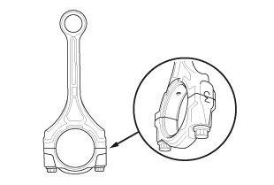
1. Inspect each connecting rod for cracks and heat damage.
2. Each connecting rod has a tolerance ranges from 0 to 0.024 mm (0.00095 in), in 0.006 mm (0.00024 in) increments, depending on the size of its big end bore. It is then stamped with a number (1, 2, 3, or 4) indicating the range. You may find any combination of numbers in any engine. (Half the number is stamped on the connecting rod, the other half is on the rod cap.) If you cannot read the code because of an accumulation of oil and varnish, do not scrub it with a wire brush or scraper. Clean it only with solvent or detergent.

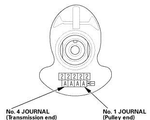
3. The connecting rod journal codes are stamped on the crankshaft.
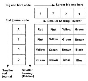
4. Use the big end bore codes and rod journal codes to select the appropriate replacement bearings from the following table.
NOTE:
* Color code is on the edge of the bearing.
* When using bearing halves of different colors, it does not matter which color is used in the top or bottom.
7. Connecting Rod Bolt - Inspection
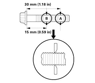
1. Measure the diameter of each connecting rod bolt at point A and point B.
2. Calculate the difference in diameter between point A and point B.

3. If the difference in diameter is out of specification, replace the connecting rod bolt.
8. Connecting Rod Caps/Bearing Halves
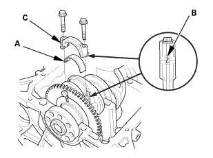
1. Install the bearing halves (A) in the connecting rods.
2. Apply new engine oil to the threads of the connecting rod bolts.
3. Seat the rod journals into connecting rod No. 1 and connecting rod No. 4. Line up the mark (B) on the connecting rod and the bearing cap (C).
4. Install the bearing caps and the bolts finger-tight.
5. Rotate the crankshaft clockwise, and seat the journals into connecting rod No. 2 and connecting rod No. 3. Line up the mark on the connecting rod and the bearing cap.
6. Install the bearing caps and the bolts finger-tight.
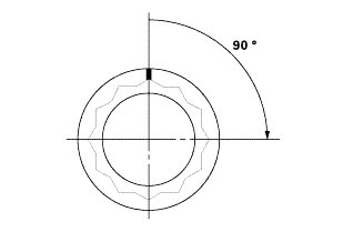
7. Torque the connecting rod bolts to 10 Nm (1.0 kgfm, 7 lbft).
8. Tighten the connecting rod bolts an additional 90 °.
NOTE: Remove the connecting rod bolt if you tightened it beyond the specified angle, inspect the connecting rod bolts. Do not loosen it back to the specified angle.
9. Crankshaft Bearing Caps/Bearing Halves
1. Remove all of the old liquid gasket from the bearing cap mating surfaces the bolts, and the bolt holes.
2. Clean and dry the bearing cap mating surfaces.
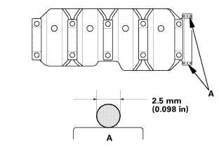
3. Apply liquid gasket (P/N 08717-0004 or 08718-0009) to the engine block mating surface of the bearing cap bridge/No. 5 bearing cap. Install the component within 5 minutes of applying the liquid gasket.
NOTE:
* Apply a 2.5 mm (0.098 in) diameter bead of liquid gasket along the broken line (A).
* If too much time has passed after applying the liquid gasket, remove the old liquid gasket and residue, then reapply new liquid gasket.
4. Put the bearing cap bridge on the engine block.
5. Apply new engine oil to the threads of the bearing cap bridge bolts.
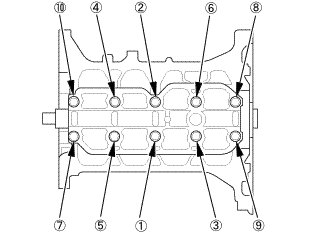
6. Torque the bearing cap bolts in sequence to 25 Nm (2.5 kgfm, 18 lbft).
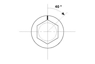
7. Tighten the bearing cap bolts an additional 40 °.
8. Clean the excess liquid gasket off the engine block.