Part 2
Service Information
Cylinder Bore Honing
10. Crankshaft Oil Seal Transmission Side
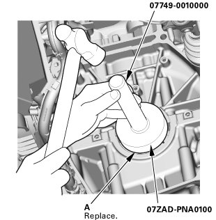
1. Clean and dry the crankshaft oil seal housing.
2. Apply a light coat of new engine oil to the lip of the crankshaft oil seal.
3. Use the driver handle, 15 x 135L, and the oil seal driver attachment, 96 mm, to drive a new crankshaft oil seal (A) squarely into the block to the specified installed height.
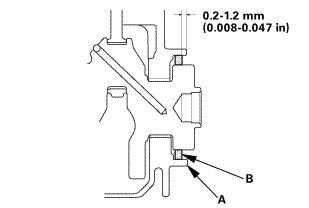
4. Measure the distance between the cylinder block (A) and the oil seal (B).

11. Engine Oil Pump Assembly
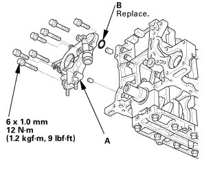
1. Clean the O-ring groove and the mating surface of the engine block.
2. Install the oil pump (A) with a new O-ring (B).
12. Engine Oil Strainer
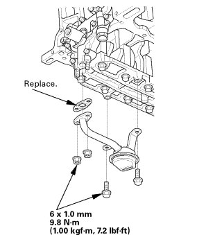
1. Install the oil strainer (A) with a new gasket.
13. OIL PAN ASSEMBLY
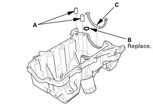
1. Remove all of the old liquid gasket from the oil pan mating surfaces, the bolts, and the bolt holes.
2. Clean and dry the oil pan mating surfaces.
3. Install the dowel pins (A), a new O-ring (B) and the oil pan gasket (C) on the oil pan.
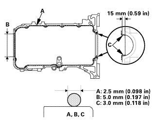
4. Apply liquid gasket (P/N 08717-0004 or 08718-0009) to the engine block mating surface of the oil pan and to the inner threads of the bolt holes. Install the component within 5 minutes of applying the liquid gasket.
NOTE:
* Apply a 2.5 mm (0.098 in) diameter bead of liquid gasket along the broken line (A).
* Apply a 5.0 mm (0.197 in) diameter bead of liquid gasket to the shaded area (B).
* Apply a 3.0 mm (0.118 in) diameter bead of liquid gasket to the broken line (C).
* If too much time has passed after applying the liquid gasket, remove the old liquid gasket and residue, then reapply new liquid gasket.
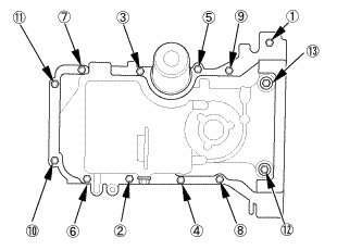
5. Install the oil pan (B) with new O-rings (C).
NOTE: Raise the oil pan carefully not to damage IMA motor (resolver stator).
6. Tighten the bolts in three steps. Wipe off the excess liquid gasket from the crankshaft pulley end and the flywheel.

14. Set The Crankshaft to Top Dead Center
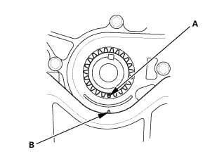
1. Set the crankshaft to top dead center (TDC). Align the TDC mark (A) on the crankshaft sprocket with the pointer (B) on the oil pump.
15. Set the No.1 Piston at Top Dead Center (Without Cam Chain Case/Oil Pump)
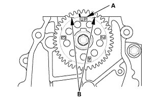
1. Set the camshaft TDC. The "UP" mark (A) on the camshaft sprocket should be at the top, and the TDC grooves (B) on the camshaft sprocket should line up with the top edge of the head.
16. Cylinder Head Assembly
1. Clean the cylinder head and the engine block surface.
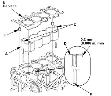
2. Install the cooling control spacer (A) in the engine block whenever the engine block is replaced.
3. Check the play of the cooling control spacer. If there is play, replace the cooling control spacer.
NOTE:
* Letting a cooling control spacer contact a water jacket base (B)
* The cooling control spacer upper end portions (C) and the clearance of the cylinder block end face (D) being more than 0.2 mm.
4. Install the new cylinder head gasket (E) and the dowel pins (F) on the engine block. Always use a new cylinder head gasket.
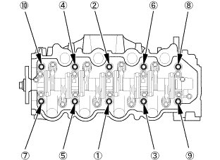
5. Install the cylinder head on the engine block.
6. Apply new engine oil to the threads and under the bolt heads of all cylinder head bolts.
7. Torque the cylinder head bolts in sequence to 29 Nm (3.0 kgf, 21 lbft) with a beam-type torque wrench if possible. When using a preset-click-type torque wrench, be sure to tighten slowly and do not overtighten. If a bolt makes any noise while you are torquing it, loosen the bolt and retighten it from the first step.
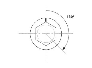
8. Tighten all cylinder head bolts an additional 130 °.
17. Cam Chain
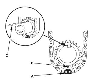
1. Install the cam chain on the crankshaft sprocket with the colored piece (A) aligned with the TDC mark (B) on the crankshaft sprocket, then install the crankshaft sprocket with the key (C) to the crankshaft.
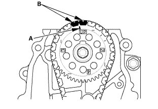
2. Install the cam chain on the camshaft sprocket with the pointer (A) aligned with the center of the two colored pieces (B).
18. Cam Chain Tensioner and Guide
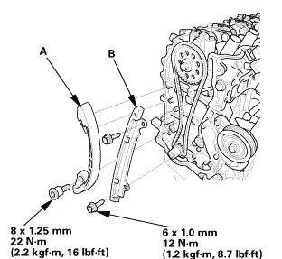
1. Install the cam chain tensioner (A) and the cam chain guide (B).
19. Cam Chain Tensioner Slider
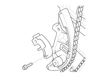
1. Install the cam chain tensioner slider, and loosely install the bolt.
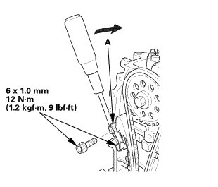
2. Apply new engine oil to the sliding surface of the cam chain tensioner slider (A).
3. Rotate the cam chain tensioner slider clockwise to compress the cam chain tensioner, and install the remaining bolt, then tighten the bolts to the specified torque.
20. Cam Chain Case
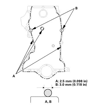
1. Remove all of the old liquid gasket from the cam chain case mating surfaces, the bolts, and the bolt holes.
2. Clean and dry the cam chain case mating surfaces.
3. Apply liquid gasket (P/N 08717-0004 or 08718-0009) to the cylinder head and the engine block mating surface of the chain case and to the inside edge of the bolt holes. Install the component within 5 minutes of applying the liquid gasket.
NOTE:
* Apply a 2.5 mm (0.098 in) diameter bead of liquid gasket along the broken line (A).
* Apply a 3.0 mm (0.118 in) diameter bead of liquid gasket to the upper surface contact areas of the engine block (B).
* If too much time has passed after applying the liquid gasket, remove the old liquid gasket and residue, then reapply new liquid gasket.
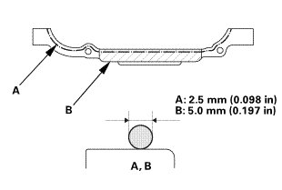
4. Apply liquid gasket (P/N 08717-0004 or 08718-0009) to the oil pan mating surface of the chain case and to the inside edge of the bolt holes. Install the component within 5 minutes of applying the liquid gasket.
NOTE:
* Apply a 2.5 mm (0.098 in) diameter bead of liquid gasket along the broken line (A).
* Apply a 5.0 mm (0.197 in) diameter bead of liquid gasket to the shaded area (B).
* If too much time has passed after applying the liquid gasket, remove the old liquid gasket and residue, then reapply new liquid gasket.
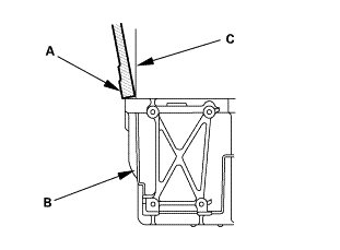
5. Set the edge of the chain case (A) on the edge of the oil pan (B), then install the chain case on the engine block (C).
NOTE:
* When installing the chain case, do not slide the bottom surface onto the oil pan mounting surface.
* Wait at least 30 minutes before filling the engine with oil.
* Do not run the engine for at least 3 hours after installing the chain case.
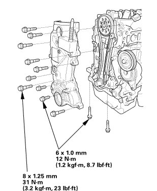
6. Tighten the chain case mounting bolts. Wipe off the excess liquid gasket from the oil pan and the chain case mating area.
21. Crankshaft Pulley
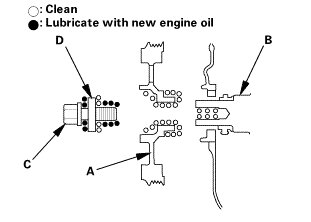
1. Clean the crankshaft pulley (A), the crankshaft (B), the bolt (C), and the washer (D).
2. Lubricate with new engine oil as shown.
3. Install the crankshaft pulley.
When a new crankshaft or a new pulley bolt is installed
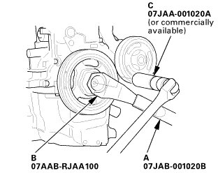
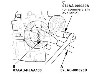
4. Hold the pulley with the holder handle (A) and the crankshaft pulley holder (B), torque the bolt to 177 Nm (18.0 kgfm, 130 lbft) with a torque wrench and a socket (C), then remove the bolt.
5. Torque the bolt to 39 Nm (4.0 kgfm, 29 lbft) with a torque wrench and a socket.
NOTE: Tighten the crankshaft pulley bolt. Do not use an impact wrench.
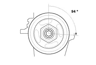
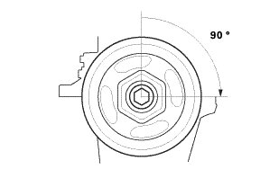
6. Tighten the bolt an additional 94 °.
When the crankshaft or the pulley bolt is reused
7. Hold the pulley with the holder handle (A) and the crankshaft pulley holder (B), then torque the bolt to 37 Nm (3.8 kgfm, 27 lbft) with a torque wrench and a socket (C).
NOTE: Tighten the crankshaft pulley bolt. Do not use an impact wrench.
8. Tighten the bolt an additional 90 °.
22. Cylinder Head Cover and/or Packing
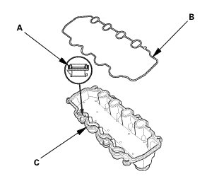
1. Check the spark plug seals (A) for damage. If the seal is damaged, replace it.
2. Thoroughly clean the head cover gasket (B) and the groove.
NOTE: Check and, if necessary, replace the head cover gasket.
3. Install the head cover gasket in the groove of the cylinder head cover (C).
4. Make sure the head cover gasket is evenly seated securely.
5. Remove the old liquid gasket from the chain case.
6. Clean the head cover contacting surfaces with a shop towel.
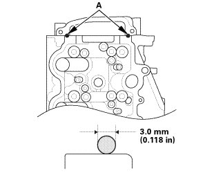
7. Apply liquid gasket (P/N 08718-0004 or 08718-0009) to the chain case contact areas (A). Install the component within 5 minutes of applying the liquid gasket.
NOTE:
* Apply a 3.0 mm (0.118 in) diameter bead of liquid gasket to the chain case contact areas.
* If too much time has passed after applying the liquid gasket, remove the old liquid gasket and residue, then reapply new liquid gasket.
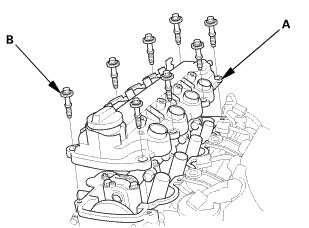
8. Place the cylinder head cover (A) on the cylinder head.
9. Slide the cover slightly back and forth to seat the head cover gasket.
NOTE:
* Wait at least 30 minutes before filing the engine with oil
* Do not run the engine for at least 3 hours after installing the head cover
10. Inspect the cover washer (B). Replace any washer that is damaged or deteriorated.
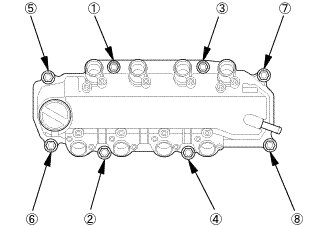
11. Torque the bolts in three steps. In the final step, torque all bolts, in sequence, to 10 Nm (1.0 kgf, 7 lbft).
23. Ignition Coil
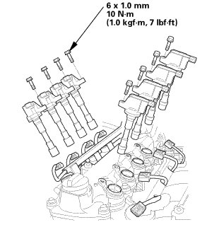
1. Install the ignition coil.
24. Thermostat Housing Assembly
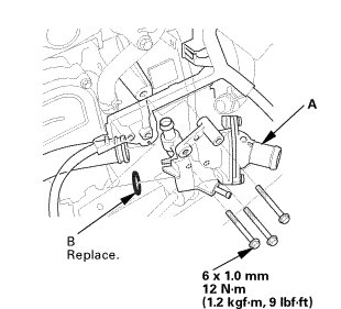
1. Install the thermostat housing assembly with new O-ring.
25. Water Pump
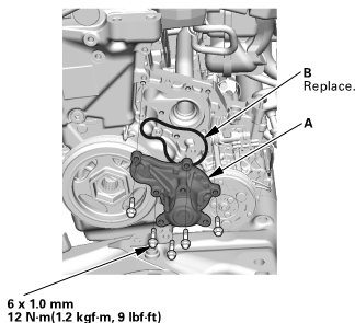
1. Inspect and clean the mating surface of the engine block.
2. Install the water pump (A) with a new O-ring (B).
26. Auto Tensioner Assembly
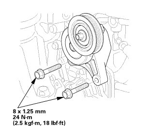
1. Install the drive belt auto-tensioner.
27. Water Pump Pulley
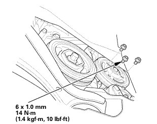
1. Install the water pump pulley.
28. WU-TWC and EGR Pipe Assembly
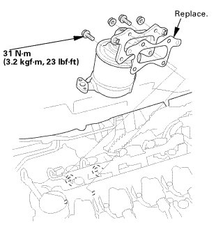
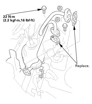
1. Install the warm up TWC assembly with new gasket.
2. Install the EGR pipe with new gaskets.
29. Exhaust Chamber Cover
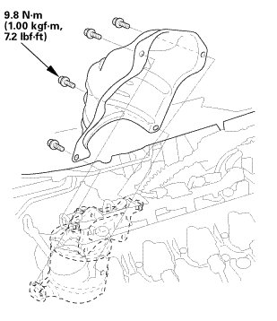
1. Install the exhaust chamber cover.
30. A/F Sensor
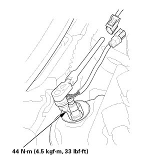
1. Install the A/F sensor.
31. Intake Manifold/Chamber and Throttle Body Assembly
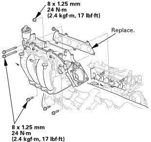
1. Install the intake manifold/chamber assembly with the throttle body and the new gasket.
32. Intake Manifold bracket
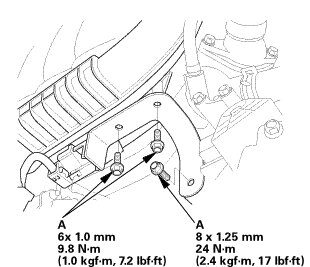
1. Install the intake manifold bracket.
33. IMA Motor Rotor Position Sensor
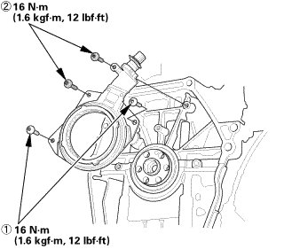
1. Install the IMA motor rotor position sensor in the numbered sequence shown.
34. IMA Motor Housing
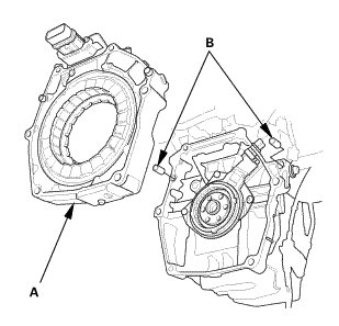
1. Install the IMA motor housing (A).
NOTE: Set dowel pins (B) to the engine before installing the motor stator on the engine.
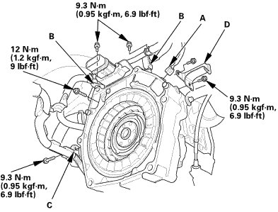
2. Install the connector (A), the stays (B), the harness clamp (C), and the heat shield (D).
35. IMA Motor Rotor
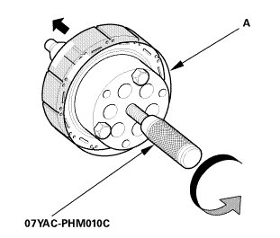
1. Attach the rotor puller on the IMA motor rotor.
2. Tape together end to end two plastic sheets (300 long by 200 wide by 0.2 mm thick) and install them around the outside of the rotor.
3. Install the IMA motor rotor to the motor stator.
NOTE:
* Before installing the rotor, make sure the handle of rotor puller is fully turned in clockwise.
* Slowly turn the handle of the rotor puller counterclockwise to insert the rotor into the stator. The rotor is drawn into the stator by magnetic force.
4. Slowly turn the handle of the rotor puller to lower and install IMA motor rotor into the motor stator.
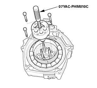
5. Remove the rotor puller.
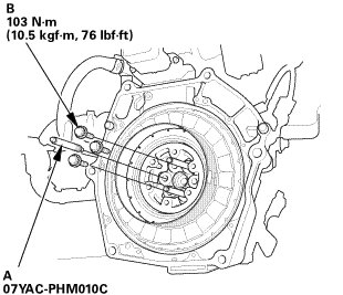
6. Remove the rotor puller guide pins (A), then install the remaining three bolts (B).
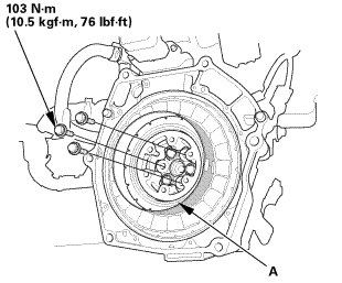
7. Install three of the six bolts as shown.
8. Remove the plastic film (A).
36. Drive Plate Assembly
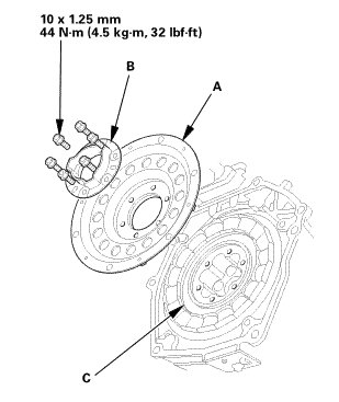
1. Install the drive plate (A) and the flywheel support (B) on the motor rotor (C), and tighten the bolts to the specified torque in a crisscross pattern in at least two or three steps.
37. CVT Flywheel
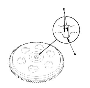
1. Wipe off the used grease in the flywheel hub cap (A) and the flywheel hub splines (B).
NOTE: Inspect the flywheel splines for wear. If splines are rounded, flat or deformed, replace the flywheel. Also check leaks.
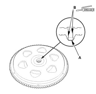
2. Fill the inside of the flywheel hub cap (A) with about 1.0 to 2.0 g (0.035 to 0.071 oz.) of Super High Temp Urea Grease.
NOTE: Do not overfill the flywheel hub cap with grease.
3. Coat the flywheel hub splines (B) with Super High Temp Urea Grease.
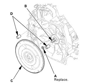
4. Install a new sealing ring (A) on the input shaft (B).
5. Install the flywheel (C) on the input shaft, then install the dowel pins (D).
38. CVT Transmission Assembly
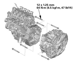
1. Install the CVT transmission assembly.
39. Starter
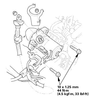
1. Install the starter.
40. Engine Wire Harness
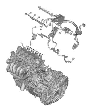
1. Install the engine wire harness.