Timing Chain: Service and Repair
Service Information
Cam Chain Removal and Installation
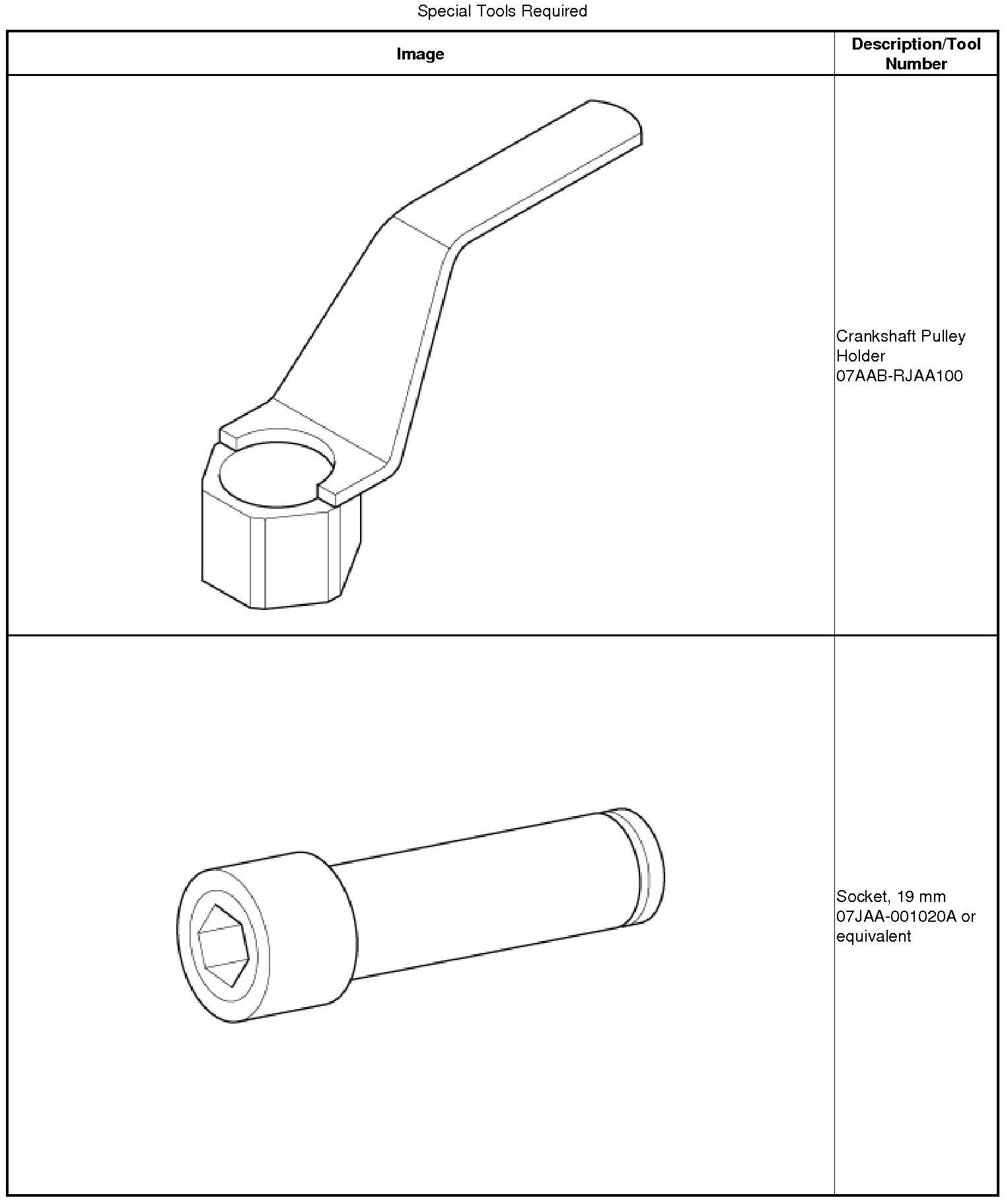
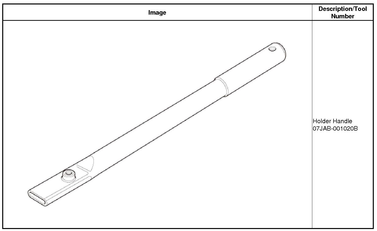
Removal
Keep the cam chain away from magnetic fields.
1. Vehicle - Lift
1. Raise the vehicle on a lift, and make sure it is securely supported.
2. Engine Cover
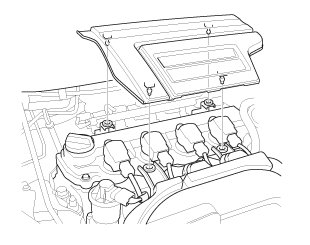
1. Remove the engine cover.
3. Ignition Coil
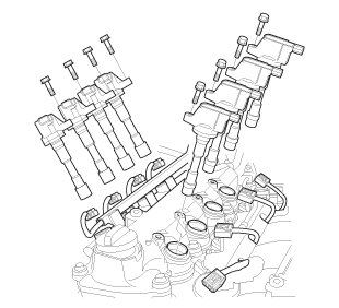
1. Disconnect the connectors.
2. Remove the ignition coils.
4. Cylinder Head Cover Peripheral Assembly
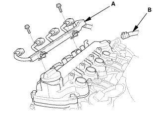
1. Remove the harness holder (A).
2. Disconnect the breather hose (B).
5. Cylinder Head Cover and/or Packing
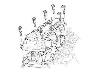
1. Remove the cylinder head cover.
6. Check the No.1 Piston at Top Dead Center (With Cam Chain Case/Oil Pump)
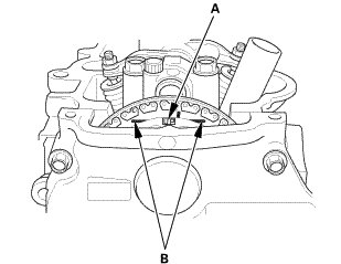
1. Set the No. 1 piston at top dead center (TDC). The "UP" mark (A) on the camshaft sprocket should be at the top, and the TDC grooves (B) on the camshaft sprocket should line up with the top edge of the head.
7. Tire and Wheel-Removal, Front Right
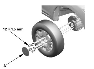
1. Remove the center cap (A).
2. Remove the right front wheel.
8. Splash Shield
1. Remove the splash shield (A).
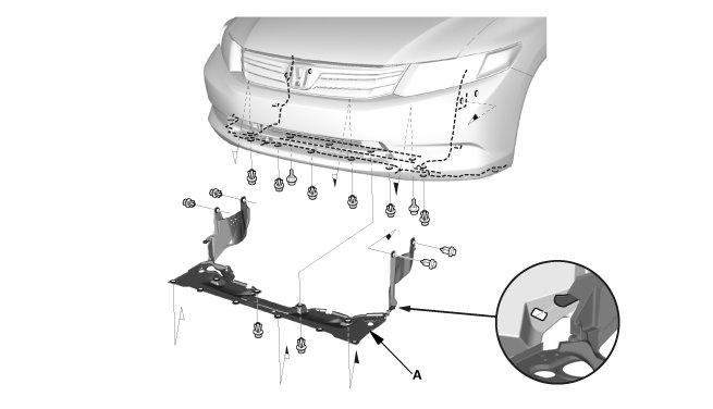
9. Engine Undercover
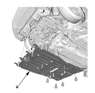
1. Remove the engine undercover (A).
10. Water Pump Pulley Mounting Bolt - Loosen
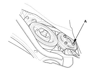
1. Loosen the water pump pulley mounting bolts (A).
11. Drive Belt
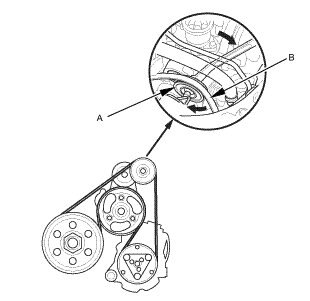
1. Move the auto-tensioner (A) to relieve tension from the drive belt (B).
2. Remove the drive belt.
12. Water Pump Pulley
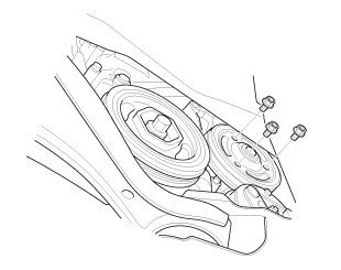
1. Remove the water pump pulley.
13. Crankshaft Pulley
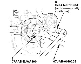
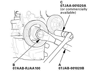
1. Hold the pulley with the holder handle (A) and the crankshaft pulley holder (B).
2. Remove the bolt with a socket, 19 mm (C) and a breaker bar.
3. Remove the crankshaft pulley.
14. Engine Jack Support (State Of A Low Vehicle)
1. Lift and support the engine with a jack and a wood block under the oil pan.
15. Side Engine Mount
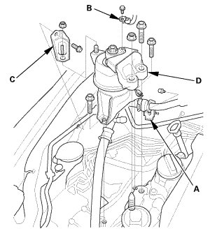
1. Remove the A/C pipe bracket (A).
2. Remove the ground cable (B).
3. Remove the side engine mount bracket (C) and the side engine mount assembly (D).
16. Cam Chain Case

1. Remove the cam chain case.
17. Cam Chain Inspection
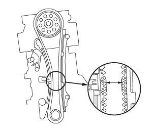
1. Measure the cam chain separation. If the distance is less than the service limit, replace the cam chain and the cam chain tensioner.

18. Cam Chain Tensioner Slider
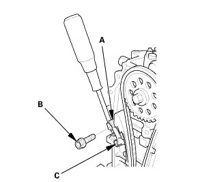
1. Apply new engine oil to the sliding surface of the cam chain tensioner slider (A).
2. Hold the cam chain tensioner slider with a screwdriver, then remove the upper bolt (B), and loosen the lower bolt (C).
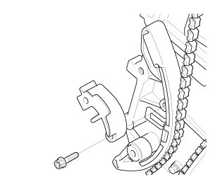
3. Remove the cam chain tensioner slider.
19. Cam Chain Tensioner and Guide
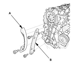
1. Remove the cam chain tensioner (A) and the cam chain guide (B).
20. Cam Chain
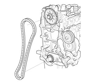
1. Remove the cam chain.
Installation
Keep the cam chain away from magnetic fields.
1. Set The Crankshaft to Top Dead Center

1. Set the crankshaft to top dead center (TDC). Align the TDC mark (A) on the crankshaft sprocket with the pointer (B) on the oil pump.
2. Set the No.1 Piston at Top Dead Center (Without Cam Chain Case/Oil Pump)

1. Set the camshaft TDC. The "UP" mark (A) on the camshaft sprocket should be at the top, and the TDC grooves (B) on the camshaft sprocket should line up with the top edge of the head.
3. Cam Chain

1. Install the cam chain on the crankshaft sprocket with the colored piece (A) aligned with the TDC mark (B) on the crankshaft sprocket, then install the crankshaft sprocket with the key (C) to the crankshaft.

2. Install the cam chain on the camshaft sprocket with the pointer (A) aligned with the center of the two colored pieces (B).
4. Cam Chain Tensioner and Guide

1. Install the cam chain tensioner (A) and the cam chain guide (B).
5. Cam Chain Tensioner Slider
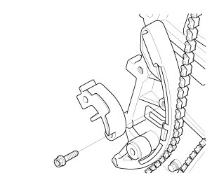
1. Install the cam chain tensioner slider, and loosely install the bolt.
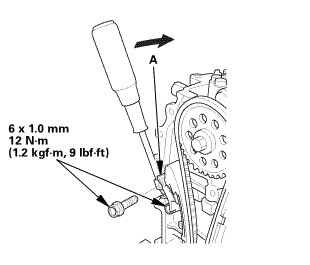
2. Apply new engine oil to the sliding surface of the cam chain tensioner slider (A).
3. Rotate the cam chain tensioner slider clockwise to compress the cam chain tensioner, and install the remaining bolt, then tighten the bolts to the specified torque.
6. Cam Chain Case
1. Check the cam chain case oil seal for damage. If the oil seal is damaged, replace the cam chain case oil seal.
2. Remove all of the old liquid gasket from the cam chain case mating surfaces, the bolts, and the bolt holes.
3. Clean and dry the cam chain case mating surfaces.
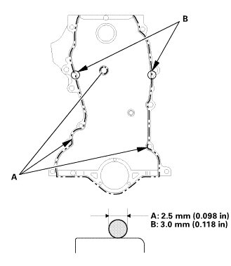
4. Apply liquid gasket (P/N 08718-0004 or 08718-0009) to the cylinder head and the engine block mating surface of the chain case and to the inside edge of the bolt holes. Install the component within 5 minutes of applying the liquid gasket.
NOTE:
* Apply a 2.5 mm (0.098 in) diameter bead of liquid gasket along the broken line (A).
* Apply a 3.0 mm (0.118 in) diameter bead of liquid gasket to the upper surface contact areas of the engine block (B).
* If too much time has passed after applying the liquid gasket, remove the old liquid gasket and residue, then reapply new liquid gasket.
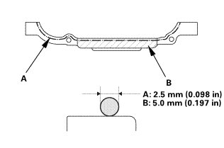
5. Apply liquid gasket (P/N 08718-0004 or 08718-0009) to the oil pan mating surface of the chain case and to the inside edge of the bolt holes. Install the component within 5 minutes of applying the liquid gasket.
NOTE:
* Apply a 2.5 mm (0.098 in) diameter bead of liquid gasket along the broken line (A).
* Apply a 5.0 mm (0.20 in) diameter bead of liquid gasket to the shaded area (B).
* If too much time has passed after applying the liquid gasket, remove the old liquid gasket and residue, then reapply new liquid gasket.
7. Cylinder Head Cover and/or Packing
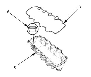
1. Check the spark plug seals (A) for damage. If the seal is damaged, replace it.
2. Thoroughly clean the head cover gasket (B) and the groove.
NOTE: Check and, if necessary, replace the head cover gasket.
3. Install the head cover gasket in the groove of the cylinder head cover (C).
4. Make sure the head cover gasket is evenly seated securely.
5. Remove the old liquid gasket from the chain case.
6. Clean the head cover contacting surfaces with a shop towel.
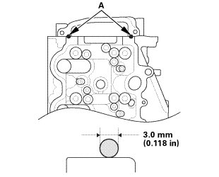
7. Apply liquid gasket (P/N 08718-0004 or 08718-0009) to the chain case contact areas (A). Install the component within 5 minutes of applying the liquid gasket.
NOTE:
* Apply a 3.0 mm (0.118 in) diameter bead of liquid gasket to the chain case contact areas.
* If too much time has passed after applying the liquid gasket, remove the old liquid gasket and residue, then reapply new liquid gasket.
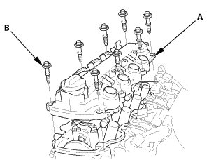
8. Place the cylinder head cover (A) on the cylinder head.
9. Slide the cover slightly back and forth to seat the head cover gasket.
NOTE:
* Wait at least 30 minutes before filing the engine with oil
* Do not run the engine for at least 3 hours after installing the head cover
10. Inspect the cover washer (B). Replace any washer that is damaged or deteriorated.
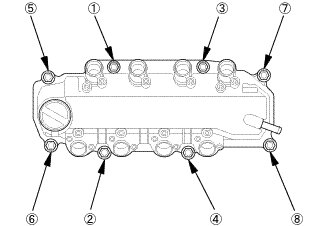
11. Torque the bolts in three steps. In the final step, torque all bolts, in sequence, to 10 Nm (1.0 kgf, 7 lb.ft).
8. Cylinder Head Cover Peripheral Assembly
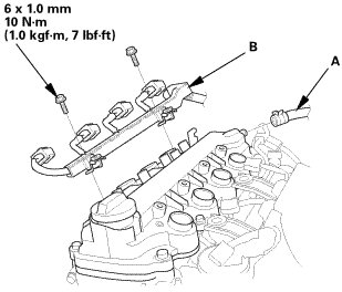
1. Connect the breather hose (A).
2. Install the harness holder (B).
9. Ignition Coil
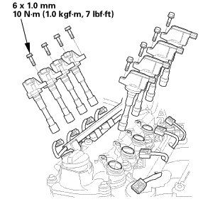
1. Install the ignition coils.
2. Connect the connectors.
10. Engine Cover
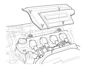
1. Install the engine cover.
11. Side Engine Mount
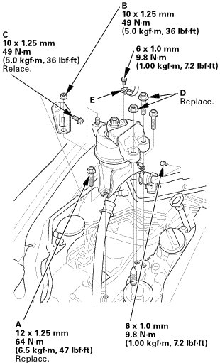
1. Tighten the new side engine mount mounting bolts (A), the side engine mount bracket nut (B), and the new bolt (C).
2. Loosely install the new side engine mount bracket mounting bolt/nut (D).
3. Install the ground cable (E).
4. Install the A/C pipe bracket.
12. Transmission Mount Bracket Mounting Bolt - Loosen
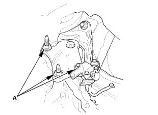
1. Loosen the transmission mount bracket support bolt and nuts (A).
13. Engine Jack Support (State Of A Low Vehicle)
1. Remove the jack and the wood block.
14. Lower Torque Rod - Loosen
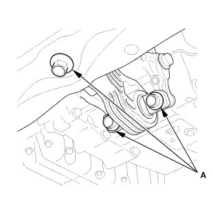
1. Loosen the lower torque rod mounting bolts (A).
15. Side Engine Mount - Tighten
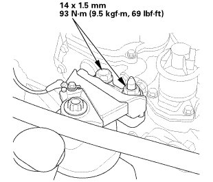
1. Tighten the side engine mount bracket mounting bolt and nut.
16. Transmission Mount Bracket Mounting Bolt - Tighten
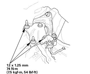
1. Tighten the transmission mount bracket support bolt and nuts.
17. Lower Torque Rod Mounting Bolt - Tighten
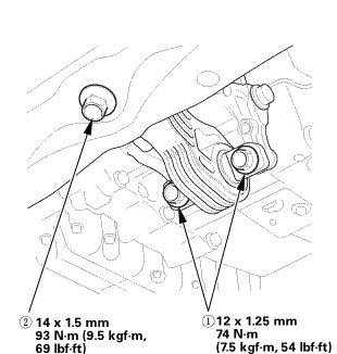
1. Tighten the lower torque rod mounting bolts in the numbered sequence shown.
18. Crankshaft Pulley
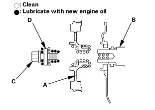
1. Clean the crankshaft pulley (A), the crankshaft (B), the bolt (C), and the washer (D).
2. Lubricate with new engine oil as shown.
3. Install the crankshaft pulley.
When a new crankshaft or a new pulley bolt is installed
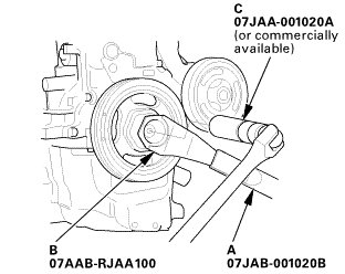
4. Hold the pulley with the holder handle (A) and the crankshaft pulley holder (B), torque the bolt to 177 Nm (18.0 kgfm, 130 lbft) with a torque wrench and a socket (C), then remove the bolt.
5. Torque the bolt to 39 Nm (4.0 kgfm, 29 lbft) with a torque wrench and a socket.
NOTE: Tighten the crankshaft pulley bolt. Do not use an impact wrench.
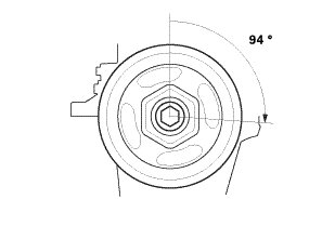
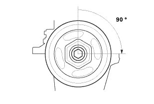
6. Tighten the bolt an additional 94 °.
When the crankshaft or the pulley bolt is reused
7. Hold the pulley with the holder handle (A) and the crankshaft pulley holder (B), then torque the bolt to 37 Nm (3.8 kgfm, 27 lbft) with a torque wrench and a socket (C).
NOTE: Tighten the crankshaft pulley bolt. Do not use an impact wrench.
8. Tighten the bolt an additional 90 °.
19. Water Pump Pulley
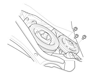
1. Install the water pump pulley.
2. Loosely install the water pump pulley mounting bolts.
20. Drive Belt
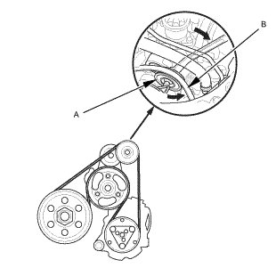
1. Move the auto-tensioner (A).
2. Install the drive belt (B).
21. Water Pump Pulley Mounting Bolt - Tighten
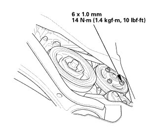
1. Tighten the water pump pulley mounting bolts.
22. Engine Undercover
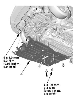
1. Install the engine undercover (A).
23. Splash Shield
1. Install the splash shield (A).
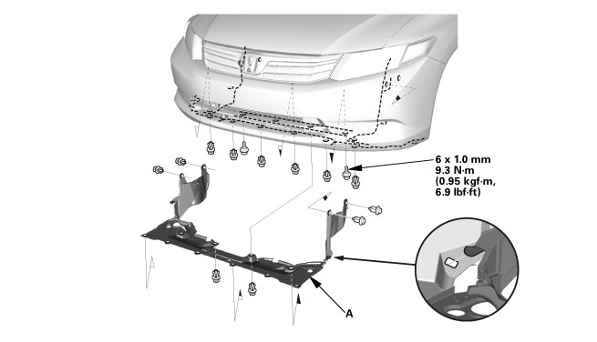
24. Tire and Wheel-Installation, Front Right
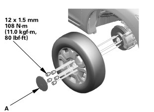
1. Install the right front wheel.
NOTE: Before installing the wheel, clean the mating surfaces between the brake disk and the inside of the wheel.
2. Install the center cap (A).
25. HDS DLC - Connection
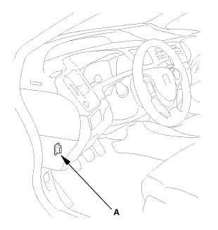
1. Connect the HDS to the data link connector (DLC) (A) located under the driver's side of the dashboard.
2. Turn the ignition switch to ON (II).
3. Make sure the HDS communicates with vehicle. If it does not communicate, go to the DLC circuit troubleshooting.
26. CKP Pattern Clear/CKP Pattern Learn
1. Select CRANK PATTERN in the ADJUSTMENT MENU with the HDS.
2. Select CRANK PATTERN CLEAR, and clear the CKP pattern.
3. Select CRANK PATTERN LEARNING with the HDS, and follow the screen prompts.