Part 3
Service Information
Heater Unit/Core Removal and Installation
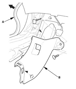
13. Both Kick Panels
Driver's side
Passenger's side
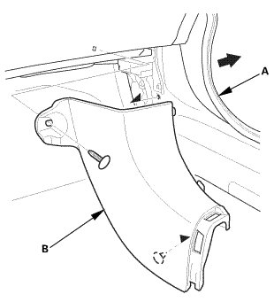
1. Pull out both front door opening seals (A) as needed.
2. Remove both kick panels (B).
14. Glove Box - Move
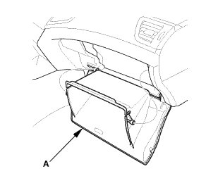
1. Lower the glove box (A).
15. Center Console Panel
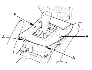
1. Detach the clips (A).
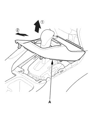
2. Remove the center console panel (A) in the order shown.
16. Cup Holder Panel Assembly
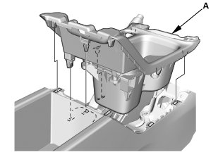
1. Remove the cup holder panel assembly (A).
17. Center Console
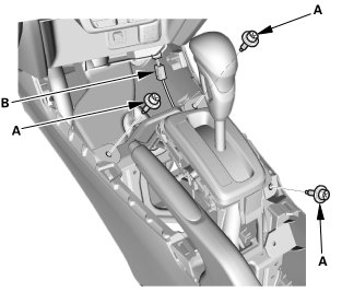
1. Remove the bolts (A).
2. Disconnect the connector (B).
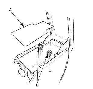
3. Remove the console box mat (A).
4. Remove the bolts (B).
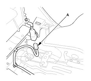
5. Disconnect the connector (A).
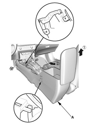
6. Remove the center console (A).
18. Rear Heater Joint Duct
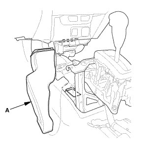
1. Remove the rear heater joint duct (A).
19. Driver's Airbag
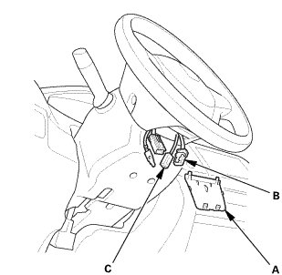
1. Remove the access panel (A).
2. Disconnect the driver's airbag inflator connector (B) on the cable reel harness.
3. Disconnect the horn switch connector (C).
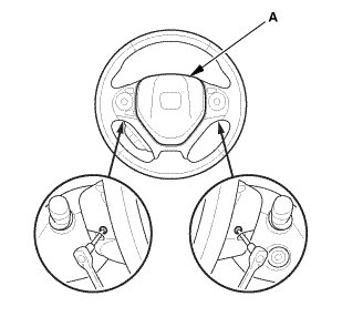
4. Remove the TORX bolts using a TORX T30 bit.
5. Remove the driver's airbag (A).
20. Steering Wheel Assembly
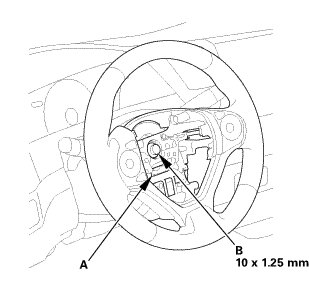
1. Set the front wheels in the straight ahead position.
2. Disconnect the connector (A).
3. Loosen the steering wheel bolt (B) three turns.
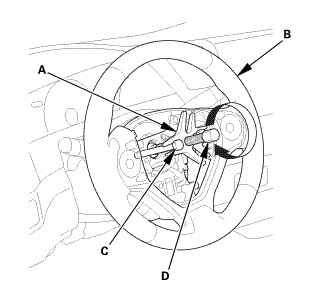
4. Install a commercially available steering wheel puller (A) on the steering wheel (B).
5. Free the steering wheel from the steering column shaft by turning the pressure bolt (C) of the puller.
Note these items when removing the steering wheel:
* Do not tap on the steering wheel or the steering column shaft when removing the steering wheel.
* If you thread the puller bolts (D) into the wheel hub more than five threads, the bolts will hit the cable reel and damage it. To prevent this, install a pair of jam nuts five threads up on each puller bolt.
6. Remove the steering wheel puller.
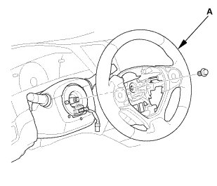
7. Remove the steering wheel (A) from the steering column.
21. Upper Column Cover
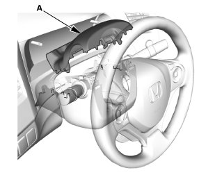
1. Remove the upper column cover (A).
22. Lower Column Cover
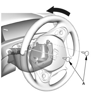
1. Remove the screws (A).
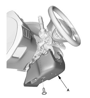
2. Remove the lower column cover (A).
23. Combination Switch Body Assembly
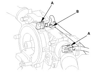
1. Disconnect the connectors (A).
2. Remove the clip (B).
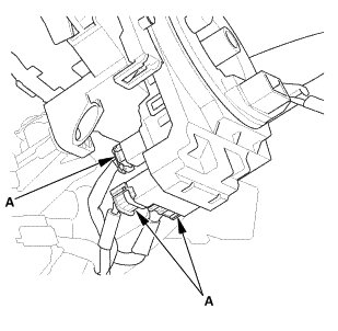
3. Disconnect the connectors (A).
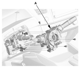
4. Remove the combination switch body assembly (A) from the steering column shaft.
24. Steering Joint Cover
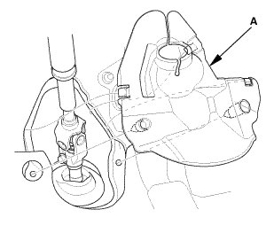
1. Remove the steering joint cover (A).
25. Steering Column Lower Slide Shaft - Hold
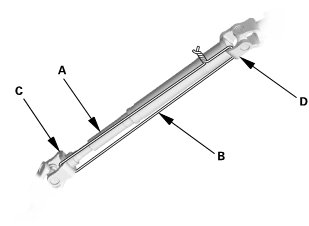
1. Set the steering column to the center tilt position, and to the center telescopic position.
2. Hold the lower slide shaft (A) on the column with a piece of wire (B) between the joint yoke (C) of the lower slide shaft and joint yoke (D) of the upper shaft to prevent the lower slider shaft from pulling out.
26. Steering Joint Bolt - Loosen
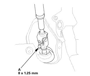
1. Loosen the steering joint bolt (A).
27. Steering Joint - Disconnection
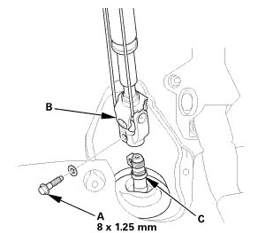
1. Remove the steering joint bolt (A).
2. Disconnect the steering joint (B) from the pinion shaft.
NOTE:
* If the center guide (C) is in place and has not moved, leave it in place.
* If the center guide has come off, discard it.
28. Steering Column
1. Disconnect the connectors (A) from the ignition switch (B).
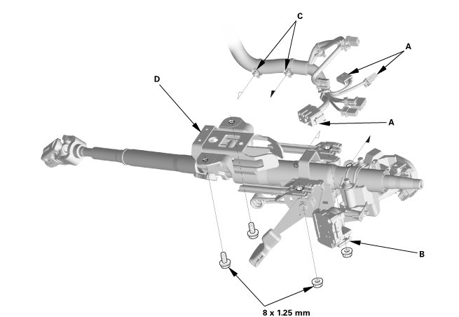
2. Detach the wire harness clips (C) from the steering column.
3. Remove the steering column (D).
NOTE: Do not release the lock lever until the steering column is installed. If the lock lever is released before installation, adjust the steering column after installation.
29. A-Pillar Corner Trim Both
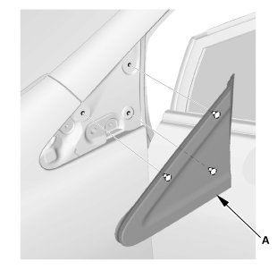
1. Remove both A-pillar corner trims (A).
30. Dashboard/Steering Hanger Beam
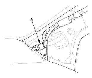
1. Disconnect the connector (A).
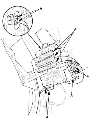
2. Disconnect the connectors (A).
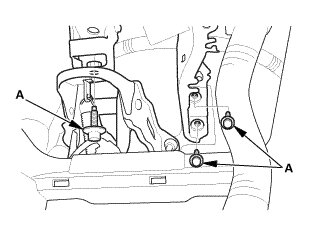
3. Remove the bolts (A) from under the dash.
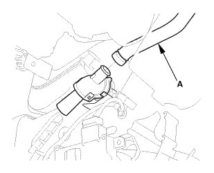
4. Remove the aspirator hose (A).
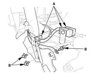
5. Disconnect the connectors (A).
6. Remove the bolts (B).
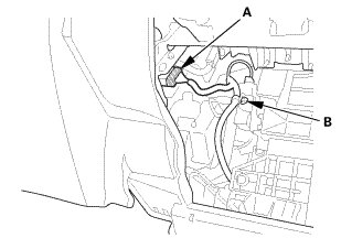
7. Disconnect the connector (A).
8. Detach the harness clip (B).
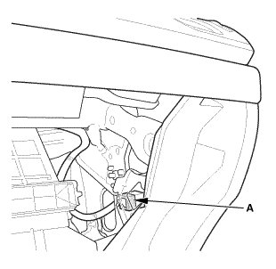
9. Disconnect the connector (A).
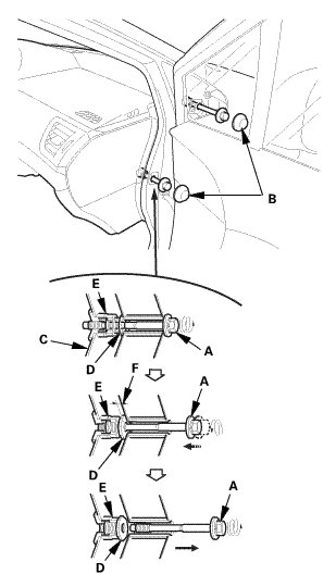
10. Remove the special bolts (A).
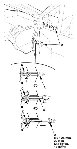
-1. Remove the caps (B).
-2. Loosen the special bolts until they disengage from the threads on the hanger beam side brackets (C) and engage the inside threads of the collar bolts (D). The thread lock on the special bolts makes the special bolts and the collar bolts turn together.
-3. Continue loosening the special bolts to turn the collar bolts into the fixed space adjusters (E) until the collar bolts engage the adjuster brackets. This creates a gap (F) between the collar bolts and the body.
-4. Loosen the special bolts to disengage them from the collar bolts. Remove the special bolts.
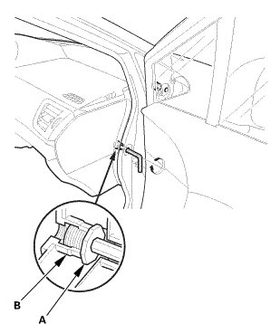
11. Check that the collar bolts (A) are seated in the fixed space adjusters (B).
NOTE: If either collar bolt was not seated, replace the special bolts.
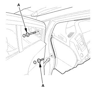
12. Remove the bolts (A).
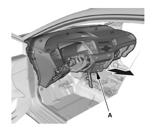
13. Remove the dashboard (A).
31. Blower-Heater Unit
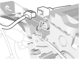
1. Disconnect the connector.
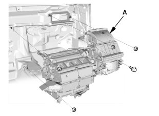
2. Remove the blower-heater unit (A).
32. A/C Wire Harness
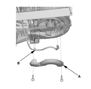
1. Remove the blower motor cover (A).
2. Disconnect the connector.
3. Detach the harness clip (B).
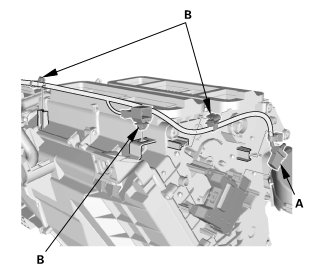
4. Disconnect the connector (A).
5. Detach the clips (B).
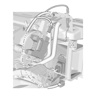
6. Disconnect the connectors.
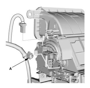
7. Detach the harness clip (A).
33. Blower Unit
1. Remove the blower unit (A).
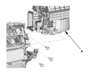
34. Passenger's Heater Duct
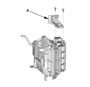
1. Remove the passenger's heater duct (A).
35. HEATER CORE COVER
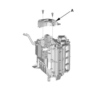
1. Remove the heater core cover (A).
36. Expansion Valve Cover
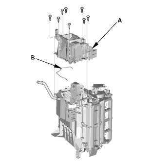
1. Remove the expansion valve cover (A) and the seal (B).
37. Heater Core
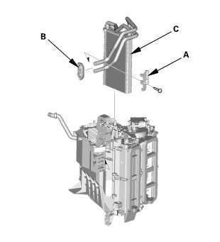
1. Remove the heater pipe bracket (A).
2. Remove the grommet (B).
3. Carefully pull out the heater core (C).
Installation
CAUTION:
* Air conditioning refrigerant or lubricant vapor can irritate your eyes, nose, or throat.
* Be careful when connecting service equipment.
* Do not breathe refrigerant or vapor.
* Do not operate the leak detector near flammable vapors. Its sensor operates at high temperatures, and could ignite the vapors, resulting in personal injury and/or damage to the equipment.
SRS components are located in this area. Review the SRS component locations Locations and the precautions and procedures Service and Repair before doing repair or servicing.
IMA components are located in this area. The IMA is a high-voltage system. You must be familiar with the IMA system before working on or around it. Make sure you have read the IMA service precautions High Voltage Safety before doing repairs or service.
NOTE:
* If an accidental system discharge occurs, ventilate the work area before resuming service.
* Additional health and safety information may be obtained from the refrigerant and lubricant manufacturers.
* Check the system for leaks using an R-134a refrigerant leak detector with an accuracy of 14 g (0.5 oz) per year or better.
* Do not interchange the inlet and outlet heater hoses, and install the hose clamps securely.
* Make sure that there is no coolant leakage.
* Make sure that there is no air leakage.
* Start the engine, and hold the engine speed between 3,500-4,000 rpm without load (in P or N) until the level gauge will display at half charged level.
1. Heater Core
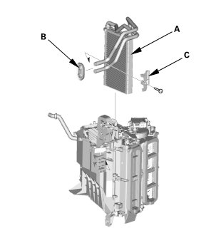
1. Carefully install the heater core (A).
2. Install the grommet (B).
3. Install the heater pipe bracket (C).
2. Expansion Valve Cover
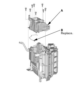
1. Install the expansion valve cover (A) and the new seal (B).
3. HEATER CORE COVER
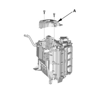
1. Install the heater core cover (A).
4. Passenger's Heater Duct
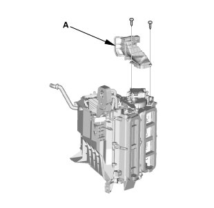
1. Install the passenger's heater duct (A).
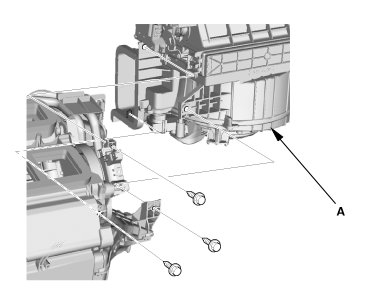
5. Blower Unit
1. Install the blower unit (A).
6. A/C Wire Harness
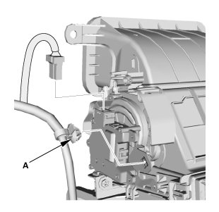
1. Install the harness clip (A).
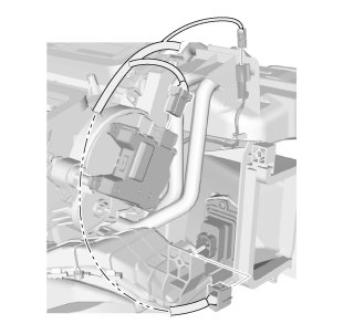
2. Connect the connectors.
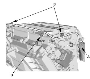
3. Connect the connector (A).
4. Install the clips (B).
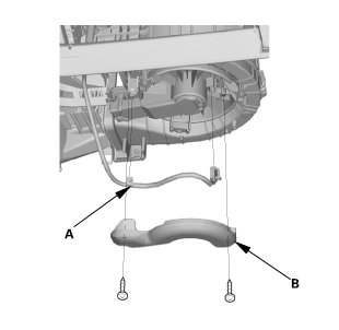
5. Connect the connector.
6. Install the harness clip (A).
7. Install the blower motor cover (B).
7. Blower-Heater Unit
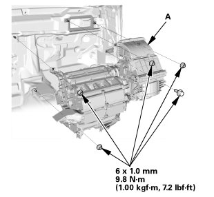
1. Install the blower-heater unit (A).
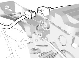
2. Connect the connector.
8. Dashboard/Steering Hanger Beam
Special bolt tightening on passenger's side
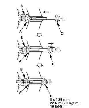
NOTE:
* Make sure the collar bolts (A) turn easily by hand in the fixed space adjusters (B). Tighten the collar bolts by hand until they engage the fixed space adjusters before reinstalling the dashboard.
* Before reinstalling the dashboard, screw the special bolts (C) into the collar bolts, and check that they turn together. If they do not turn together, replace the special bolts.
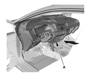
1. Install the dashboard (A).
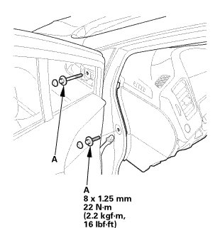
2. Install the bolts (A).