Part 4
Service Information
Heater Unit/Core Removal and Installation
3. Install the special bolts (A). As you tighten the special bolts, the collars bolts (B) screw out of fixed space adjusters (C) until they contact the body. Continue tightening the bolts to the specified torque, then install the caps (D).
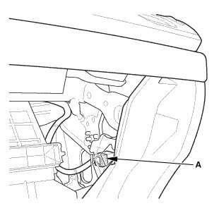
4. Connect the connector (A).
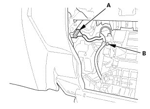
5. Connect the connector (A).
6. Install the harness clip (B).
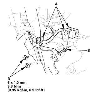
7. Connect the connectors (A).
8. Install the bolts (B).
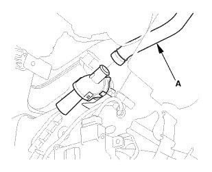
9. Install the aspirator hose (A).
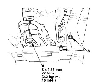
10. Install the bolts (A) under the dash.
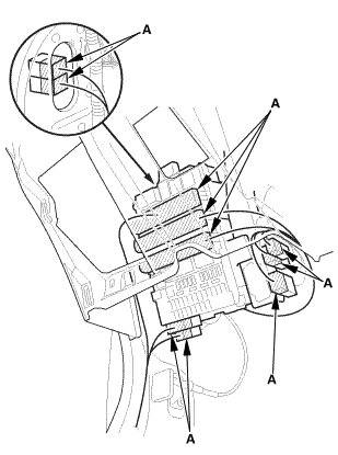
11. Connect the connectors (A).
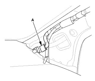
12. Connect the connector (A).
9. A-Pillar Corner Trim Both
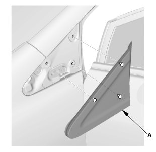
1. Install both A-pillar corner trims (A).
10. Steering Column
1. Install the steering column (A).
NOTE: Do not release the lock lever until the steering column is installed. If the lock lever is released before installation, adjust the steering column after installation.
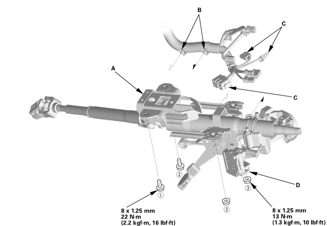
2. Loosely tighten the attaching nuts and bolts.
3. Tighten the attaching nuts and bolts to the specified torque in the sequence shown.
4. Install the wire harness clips (B) to the steering column.
5. Connect the connectors (C) to the ignition switch (D).
11. Steering Column Lower Slide Shaft - Release
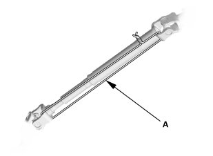
1. Cut the wire (A).
12. Steering Joint - Connection
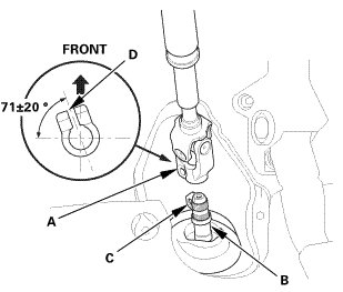
1. Set the rack in the straight ahead driving position.
2. Slip the lower end of the steering joint (A) onto the pinion shaft (B).
NOTE:
* Pinion shaft with center guide: Install the steering joint by aligning the center guide (C).
* Pinion shaft without center guide: Position the steering column by aligning the gap (D) within the angle.
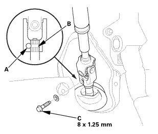
3. Align the bolt hole (A) on the steering joint with the groove (B) around the pinion shaft.
4. Loosely install the steering joint bolt (C).
5. Be sure that the joint bolt is securely in the groove in the pinion shaft.
6. Pull on the steering joint to make sure that the steering joint is fully seated.
13. Steering Joint Bolt - Tighten
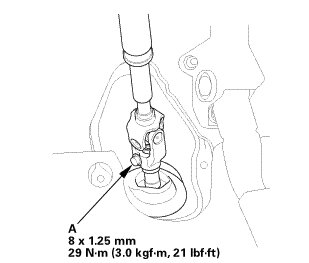
1. Tighten the steering joint bolt (A) to the specified torque.
14. Steering Joint Cover
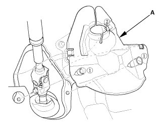
1. Install the steering joint cover (A) in the sequence shown.
15. Combination Switch Body Assembly
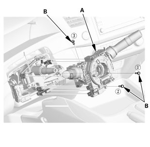
1. Install the combination switch body assembly (A).
2. Tighten three screws (B) in the sequence shown.
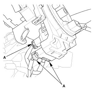
3. Connect the connectors (A).
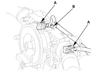
4. Connect the connectors (A).
5. Install the clip (B).
16. Lower Column Cover
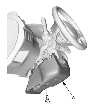
1. Install the lower column cover (A).
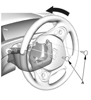
2. Install the screws (A).
17. Upper Column Cover
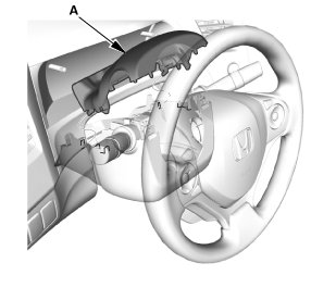
1. Install the upper column cover (A).
18. Steering Wheel Assembly
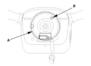
1. Make sure the front wheels are pointing straight ahead.
2. Center the cable reel (A). Do this by first rotating the cable reel clockwise until it stops.
3. Rotate the cable reel counterclockwise about three full turns. The arrow mark (B) on the cable reel label should point straight up.
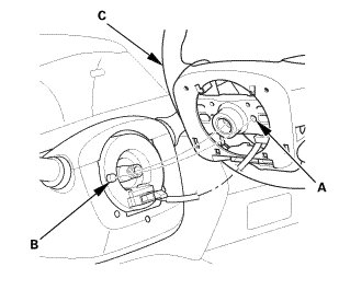
4. Position the steering wheel hub (A) so that it engages the pin (B) of the cable reel.
5. Install the steering wheel (C) on to the steering column shaft.
NOTE: Do not tap on the steering wheel or steering column shaft when installing the steering wheel.
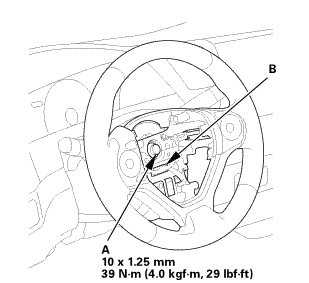
6. Install the steering wheel bolt (A), and tighten it to the specified torque.
7. Connect the connector (B).
8. Make sure the wire harness is routed and fastened properly.
19. Driver's Airbag
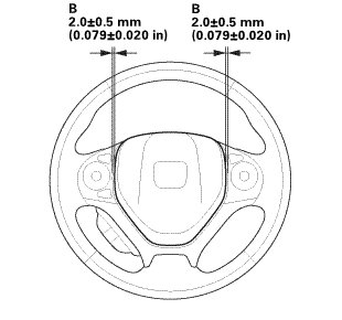
NOTE: If you are replacing a deployed driver's airbag, inspect the cable reel for heat damage. If there is any damage, replace the cable reel.
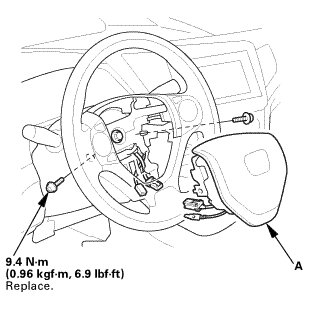
1. Place the driver's airbag (A) in the steering wheel.
2. Tighten the new TORX bolts using a TORX T30 bit.
NOTE: Make sure the clearance (B) between the steering wheel and the horn pad is the specified value.
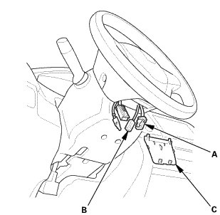
3. Connect the driver's airbag inflator connector (A) on the cable reel harness.
4. Connect the horn switch connector (B).
NOTE: After reconnecting the negative cable to the 12 volt battery, make sure the horn works properly.
5. Install the access panel (C).
20. Rear Heater Joint Duct
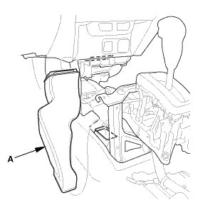
1. Install the rear heater joint duct (A).
21. Center Console
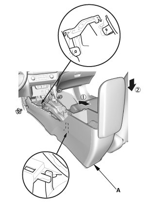
1. Install the center console (A).
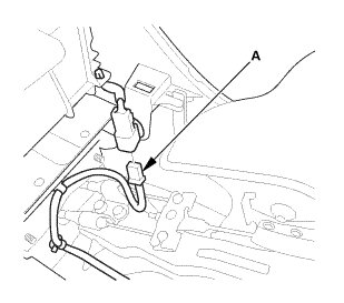
2. Connect the connector (A).
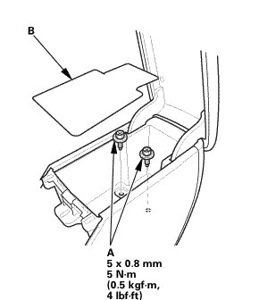
3. Install the bolts (A).
4. Install the console box mat (B).
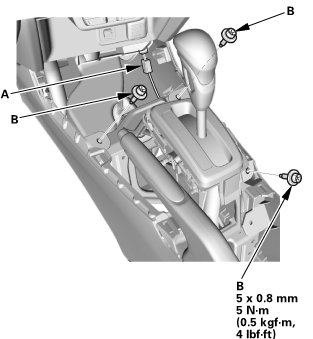
5. Connect the connector (A).
6. Install the bolts (B).
22. Cup Holder Panel Assembly
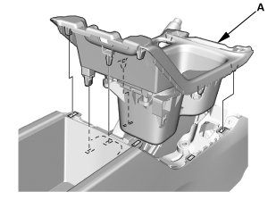
1. Install the cup holder panel assembly (A).
23. Center Console Panel
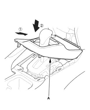
1. Install the center console panel (A) in the order shown.
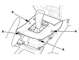
2. Install the clips (A).
24. Both Kick Panels
Driver's side
Passenger's side
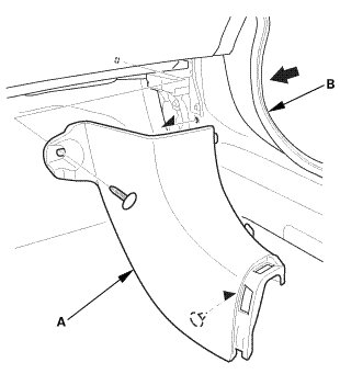
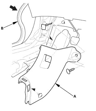
1. Install both kick panels (A).
2. Install both front door opening seals (B) as needed.
25. Both Front Door Sill Trims
Driver's side
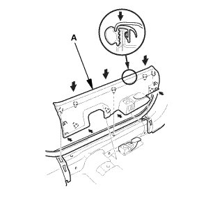
Passenger's side
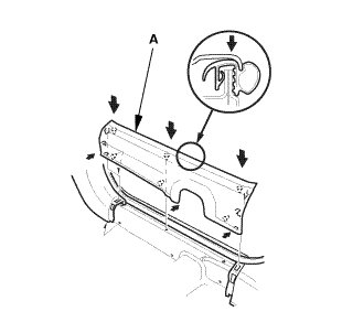
1. Install both front door sill trims (A).
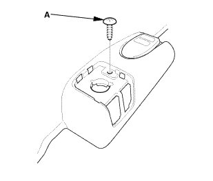
2. Driver's side: Install the screw (A).
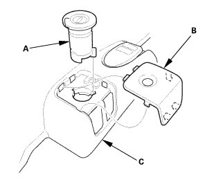
3. Driver's side: Install the opener lock cylinder (A).
4. Driver's side: Install the cap (B) to the front door sill trim (C).
26. Driver's Dashboard Lower Cover
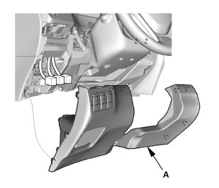
1. Connect the connectors.
2. Install the driver's dashboard lower cover (A).
27. A-Pillar Trim Both
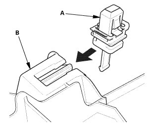
1. Carefully install the new upper clip (A) to the A-pillar trim (B).
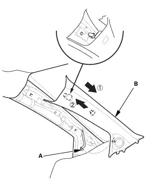
2. Connect the connector (A).
3. Fit the clips into the holes in the A-pillar.
4. Lightly push the A-pillar trim (B) into place, then install the trim.
NOTE:
* Make sure the side curtain airbag is not tucked under the clips or the trim ribs.
* Do not push too hard on the A-pillar trim. If you push too hard, the clip will be damaged, and it will not hold the trim properly.
* Gently tug on the A-pillar trim to verify that all clips are securely fastened.
5. Repeat on the opposite side.
28. Front Door Opening Seal as Needed Both
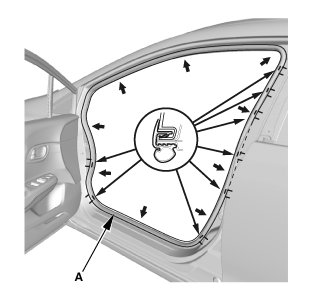
1. Install the front door opening seal (A).
2. Repeat on the opposite side.
29. Heater Hose - Body Side
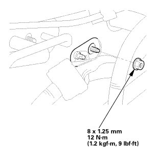
1. Install the nut.
NOTE: Take care not to damage or bend the fuel lines or brake lines, etc.
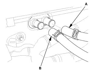
2. Connect the inlet heater hose (A).
3. Connect the outlet heater hose (B).
30. A/C Line - Evaporator Side
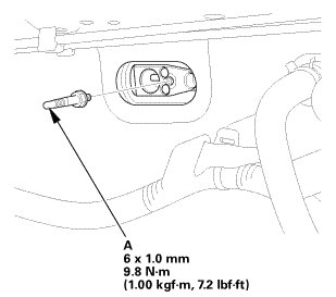
1. Install the stud bolt (A).
2. Connect the A/C line (A) with new O-rings (B) that are lubricated with clean refrigerant oil.
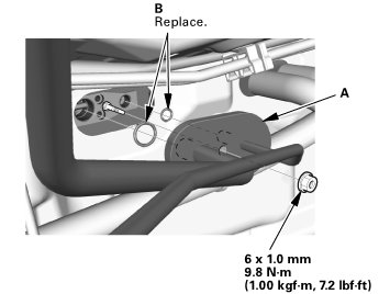
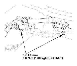
3. Install the bolts.
31. 12 Volt Battery Terminal (SRS) - Reconnection
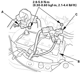
NOTE: If there is an abnormality in the performance of the 12 volt battery, test the 12 volt battery.
1. Clean the 12 volt battery terminals.
2. Connect the positive cable (A) to the 12 volt battery (B).
NOTE: Always connect the positive side first.
3. Connect the negative cable and battery sensor (C) to the 12 volt battery.
4. Apply multipurpose grease to the terminals to prevent corrosion.
32. Radiator Coolant - Refill
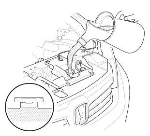
1. Pour Honda Long Life Antifreeze/Coolant Type 2 into the radiator up to the base of the filler neck.
NOTE:
* Always use Honda Long Life Antifreeze/Coolant Type 2. Using a non-Honda coolant can result in corrosion, causing the cooling system to malfunction or fail.
* Honda Long Life Antifreeze/Coolant Type 2 is a mixture of 50 % antifreeze and 50 % water. Do not add water.

2. Loosely install the radiator cap.
3. Start the engine, and let it run until it warms up (the radiator fan comes on at least twice).
4. Turn off the engine. Check the level in the radiator, and add Honda Long Life Antifreeze/ Coolant Type 2, if needed.
5. Install the radiator cap securely, then start the engine and check for leaks.
6. Clean up any spilled engine coolant.
33. A/C System Evacuation
1. Evacuate the system. The vacuum pump should run for a minimum of 30 minutes to eliminate all moisture from the system. When the suction gauge reads -93.3 kPa (-700 mmHg, -27.55 inHg) for at least 30 minutes, close all valves, and turn off the vacuum pump.
2. If the suction gauge dose not reach approximately -93.3 kPa (-700 mmHg, -27.55 inHg) in 15 minutes, there is probably a large leak in the system. Partially charge the system, and check for leaks.
34. A/C Refrigerant - Charging
1. Charge the system with the specified amount of R-134a refrigerant. Do not overcharge the system; the A/C compressor will be damaged.
Select the appropriate units of measure for your refrigerant charging station.
