CVT Pressure Test
Service Information
CVT Pressure Test
Removal
1. Vehicle - Lift
1. Raise the vehicle on a lift, and make sure it is securely supported.
2. CVT Fluid Level - Check

NOTE:
* Keep all foreign particles out of the transmission.
* Check the CVTF level within 60-90 seconds after turning the engine off.
* Higher CVTF level may be indicated if the radiator fan comes on twice or more.
1. Start the engine, and warm it up to normal operating temperature (the radiator fan comes on twice), and turn the engine off.
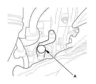
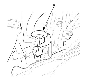
2. Remove the dipstick (yellow loop) (A) from the dipstick tube, and wipe it with a clean cloth.
3. Insert the dipstick back into the tube.

4. Remove the dipstick, and check the CVTF level. It should be between the upper mark (A) and the lower mark (B) on the HOT level in tip of the dipstick (C).
5. If the CVT fluid level is below the lower mark, check for fluid leaks at the transmission, the CVTF filter, the CVTF cooler hoses, and the CVTF cooler lines. If a problem is found, fix it before filling the transmission with CVTF.
NOTE: If the vehicle is driven when the CVTF level is below the lower mark, one or more of these symptoms may occur:
* Noise from transmission in D, S, L, and R.
* Engine runs, but vehicle does not move in any position.
* No shift to a higher ratio or lower ratio.
* Flares while driving.
* Excessive shock when accelerating and decelerating.
* Vehicle does not creep on a flat road in D, S, and L.
* Late shift after shifting from N to D or N to R.
* Unstable rpm while driving.
* Stall speed high.
6. If the level is above the upper mark, drain the CVTF to proper level.
7. If necessary, fill the transmission with CVTF through the dipstick tube opening (A) to bring the fluid level between the upper mark and the lower mark of the dipstick. Do not fill the fluid above the upper mark. Always use Honda CVTF. Using a non-Honda CVTF can affect shift quality.

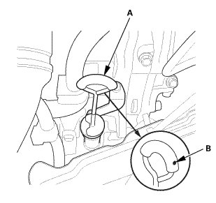
8. Insert the dipstick (A) with the dot (B) on the handle facing to the left of the vehicle.
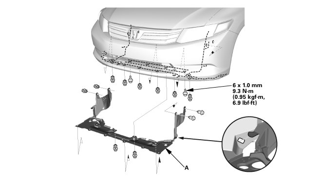
3. Splash Shield
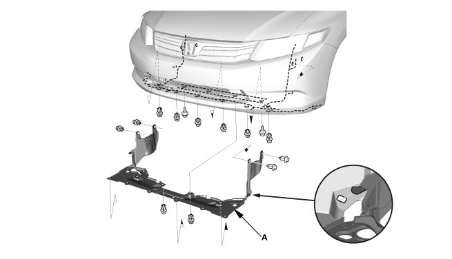
1. Remove the splash shield (A).
4. Engine Undercover
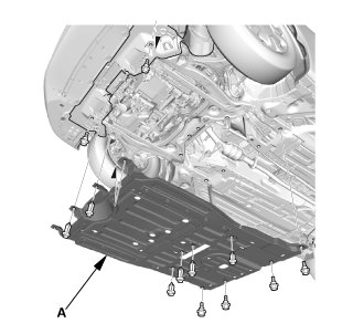
1. Remove the engine undercover (A).
Test
NOTE:
* Do not test pressure for more than 10 seconds at a time.
* Do not move the shift lever while raising the engine speed.
* Disable the VSA by pressing the VSA OFF button.
* VSA DTC(s) may come on during the test-drive. If the VSA DTC(s) come on, clear the DTC(s) after testing is done with the HDS.
1. HDS DLC - Connection
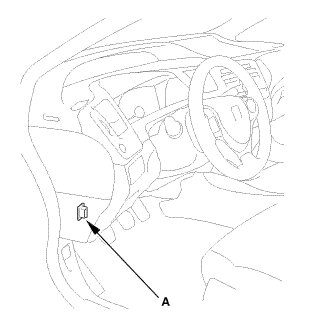
1. Connect the HDS to the data link connector (DLC) (A) located under the driver's side of the dashboard.
2. Turn the ignition switch to ON (II).
3. Make sure the HDS communicates with vehicle. If it does not communicate, go to the DLC circuit troubleshooting.
2. CVT Forward Clutch Pressure - Test
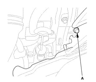
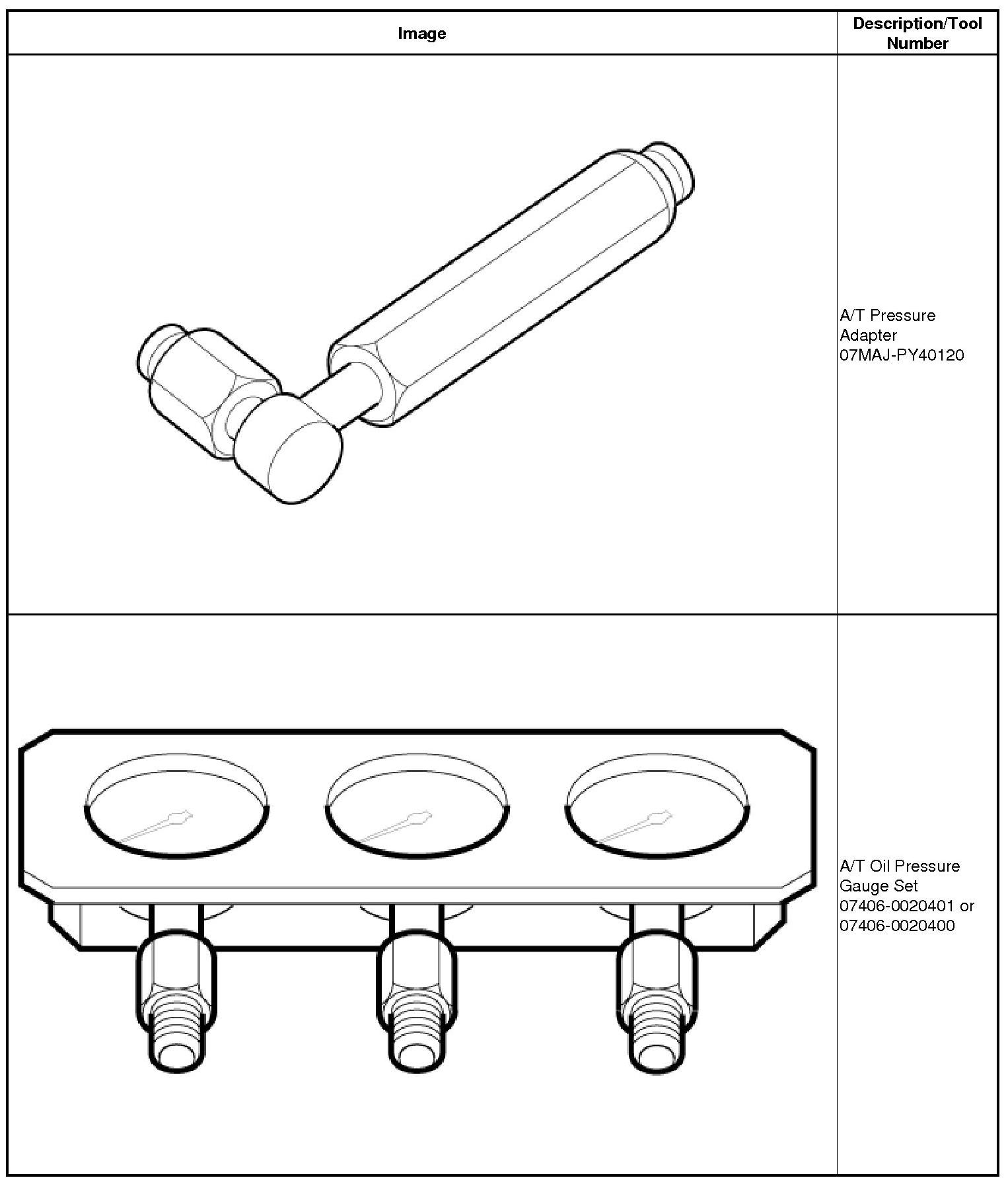
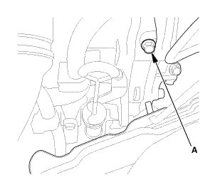
1. Connect the A/T oil pressure gauge set to the forward clutch pressure inspection port (A).
2. Start the engine, and warm up the engine to normal operating temperature (the radiator fan comes on twice).
3. Shift to D, and measure the forward clutch pressure at the forward clutch pressure inspection port while firmly pressing the brake pedal, and holding the engine speed at 1,700 rpm.

* If the pressure is out of the standard, refer to the CVT Hydraulic Controls for the pressure test problem and probable causes are listed.
4. Turn the ignition switch to LOCK (0), then disconnect the pressure gauge from the forward clutch pressure inspection port.
5. Install the sealing bolt and a new sealing washer to the forward clutch pressure inspection port, and tighten the bolt to 18 Nm (1.8 kgfm, 13 lb ft). Do not reuse the old sealing washer.
3. Reverse Brake Pressure - Test
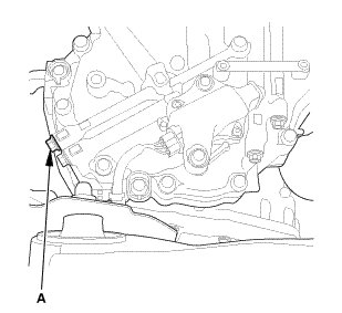
1. Connect the A/T oil pressure gauge set to the reverse brake pressure inspection port (A).
2. Start the engine, and warm up the engine to normal operating temperature (the radiator fan comes on twice).
3. Shift to R, and measure the reverse brake pressure at the reverse brake pressure inspection port while firmly pressing the brake pedal, and holding the engine speed at 1,700 rpm.

* If the pressure is out of the standard, refer to the CVT Hydraulic Controls for the pressure test problem and probable causes are listed.
4. Turn the ignition switch to LOCK (0), then disconnect the pressure gauge from the reverse brake pressure inspection port.
5. Install the sealing bolt and a new sealing washer to the reverse brake pressure inspection port, and tighten the bolt to 18 Nm (1.8 kgfm, 13 lb ft). Do not reuse the old sealing washer.
4. CVT Drive Pulley Pressure - Test
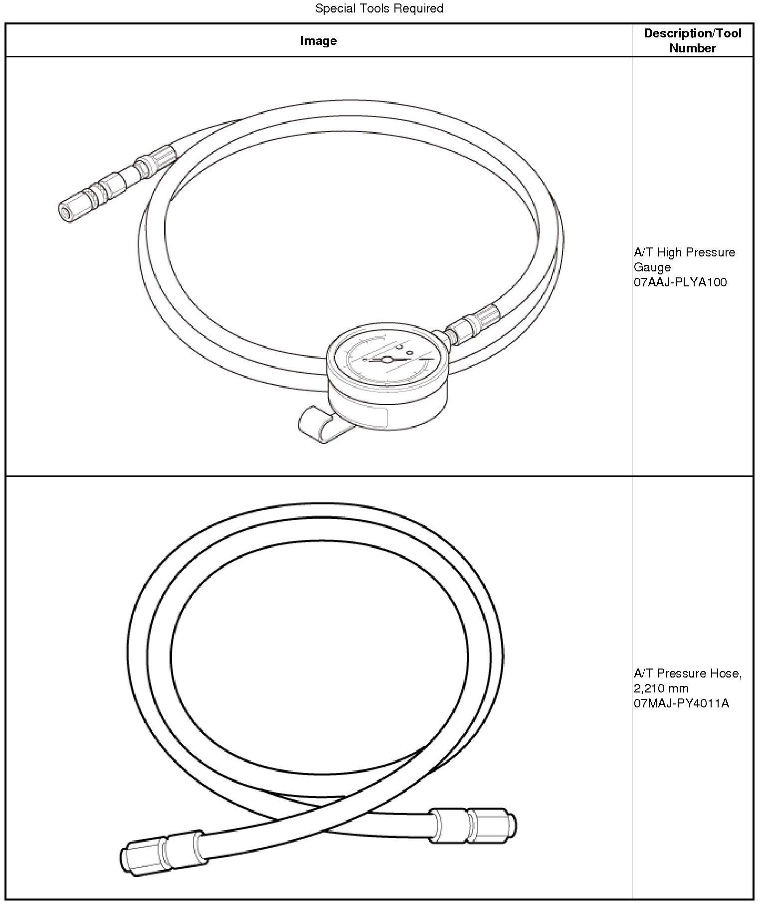
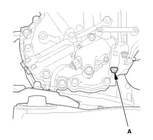
1. Connect the A/T high pressure gauge set to the drive pulley pressure inspection port (A).
2. Start the engine, and warm up the engine to normal operating temperature (the radiator fan comes on twice).
3. Shift to N, and measure the drive pulley pressure at the drive pulley pressure inspection port while firmly pressing the brake pedal, and holding the engine speed at 1,700 rpm.

* If the pressure is out of the standard, refer to the CVT Hydraulic Controls for the pressure test problem and probable causes are listed.
4. Turn the ignition switch to LOCK (0), then disconnect the pressure gauge from the drive pulley pressure inspection port.
5. Install the sealing bolt and a new sealing washer to the drive pulley pressure inspection port, and tighten the bolt to 18 Nm (1.8 kgfm, 13 lb ft). Do not reuse the old sealing washer.
5. CVT Driven Pulley Pressure - Test
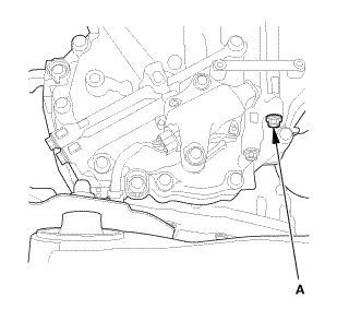
1. Connect the A/T high pressure gauge set to the driven pulley pressure inspection port (A).
2. Start the engine, and warm up the engine to normal operating temperature (the radiator fan comes on twice).
3. Shift to N, and measure the drive pulley pressure at the driven pulley pressure inspection port while firmly pressing the brake pedal, and holding the engine speed at 1,700 rpm.

* If the pressure is out of the standard, refer to the CVT Hydraulic Controls for the pressure test problem and probable causes are listed.
4. Turn the ignition switch to LOCK (0), then disconnect the pressure gauge from the driven pulley pressure inspection port.
5. Install the sealing bolt and a new sealing washer to the driven pulley pressure inspection port, and tighten the bolt to 18 Nm (1.8 kgfm, 13 lb ft). Do not reuse the old sealing washer.
6. Lubrication Pressure - Test
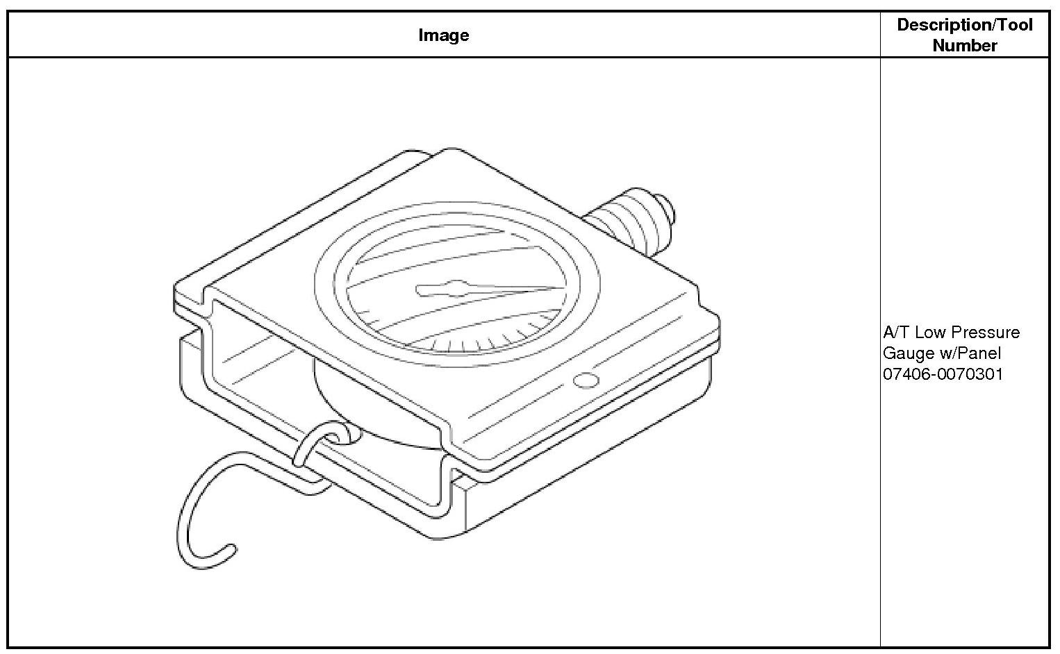
1. Connect the A/T low pressure gauge w/panel to the lubrication pressure inspection port (A).
2. Start the engine, and warm up the engine to normal operating temperature (the radiator fan comes on twice).
3. Shift to N, and measure the lubrication pressure at the lubrication pressure inspection port while firmly pressing the brake pedal, and holding the engine speed at 3,000 rpm.

* If the pressure is out of the standard, refer to the CVT Hydraulic Controls for the pressure test problem and probable causes are listed.
4. Turn the ignition switch to LOCK (0), then disconnect the pressure gauge from the lubrication pressure inspection port.
5. Install the sealing bolt and a new sealing washer to the lubrication pressure inspection port, and tighten the bolt to 18 Nm (1.8 kgfm, 13 lb ft). Do not reuse the old sealing washer.
Installation
1. Engine Undercover
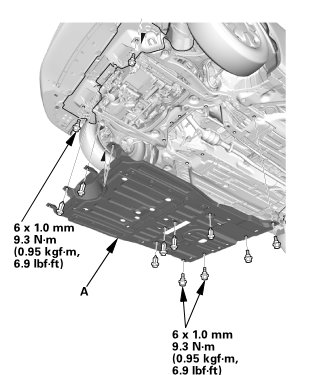
1. Install the engine undercover (A).
2. Splash Shield
1. Install the splash shield (A).
3. CVT Fluid Level - Check
NOTE:
* Keep all foreign particles out of the transmission.
* Check the CVTF level within 60-90 seconds after turning the engine off.
* Higher CVTF level may be indicated if the radiator fan comes on twice or more.
1. Park the vehicle on the level ground.
2. Start the engine, and warm it up to normal operating temperature (the radiator fan comes on twice), and turn the engine off.
3. Remove the dipstick (yellow loop) (A) from the dipstick tube, and wipe it with a clean cloth.
4. Insert the dipstick back into the dipstick tube.
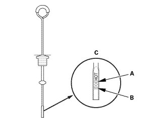
5. Remove the dipstick, and check the CVTF level. It should be between the upper mark (A) and the lower mark (B) on the HOT level in tip of the dipstick (C).
6. If the CVT fluid level is below the lower mark, check for fluid leaks at the transmission, the CVTF filter, the CVTF cooler hoses, and the CVTF cooler lines. If a problem is found, fix it before filling the transmission with CVTF.
NOTE: If the vehicle is driven when the CVTF level is below the lower mark, one or more of these symptoms may occur:
* Noise from transmission in D, S, L, and R.
* Engine runs, but vehicle does not move in any position.
* No shift to a higher ratio or lower ratio.
* Flares while driving.
* Excessive shock when accelerating and decelerating.
* Vehicle does not creep on a flat road in D, S, and L.
* Late shift after shifting from N to D or N to R.
* Unstable rpm while driving.
* Stall speed high.
7. If the level is above the upper mark, drain the CVTF to proper level.

8. If necessary, fill the transmission with CVTF through the dipstick tube opening (A) to bring the fluid level between the upper mark and the lower mark of the dipstick. Do not fill the fluid above the upper mark. Always use Honda CVTF. Using a non-Honda CVTF can affect shift quality.
9. Insert the dipstick (A) with the dot (B) on the handle facing to the left of the vehicle.