CVT Forward Clutch Clearance Inspection
Service Information
CVT Forward Clutch Clearance Inspection
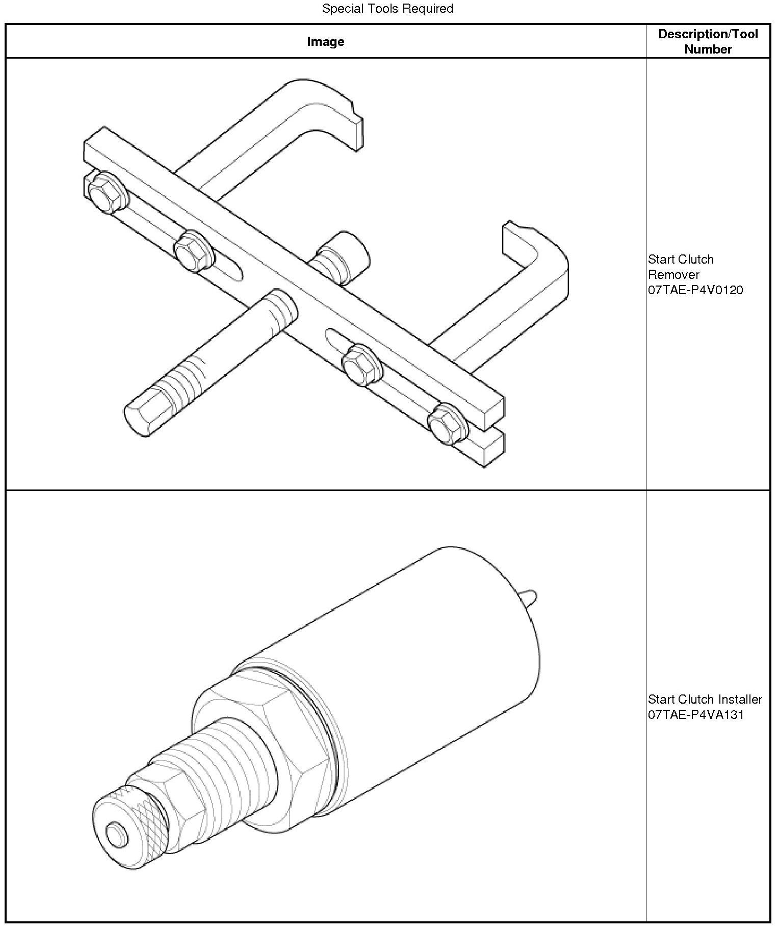
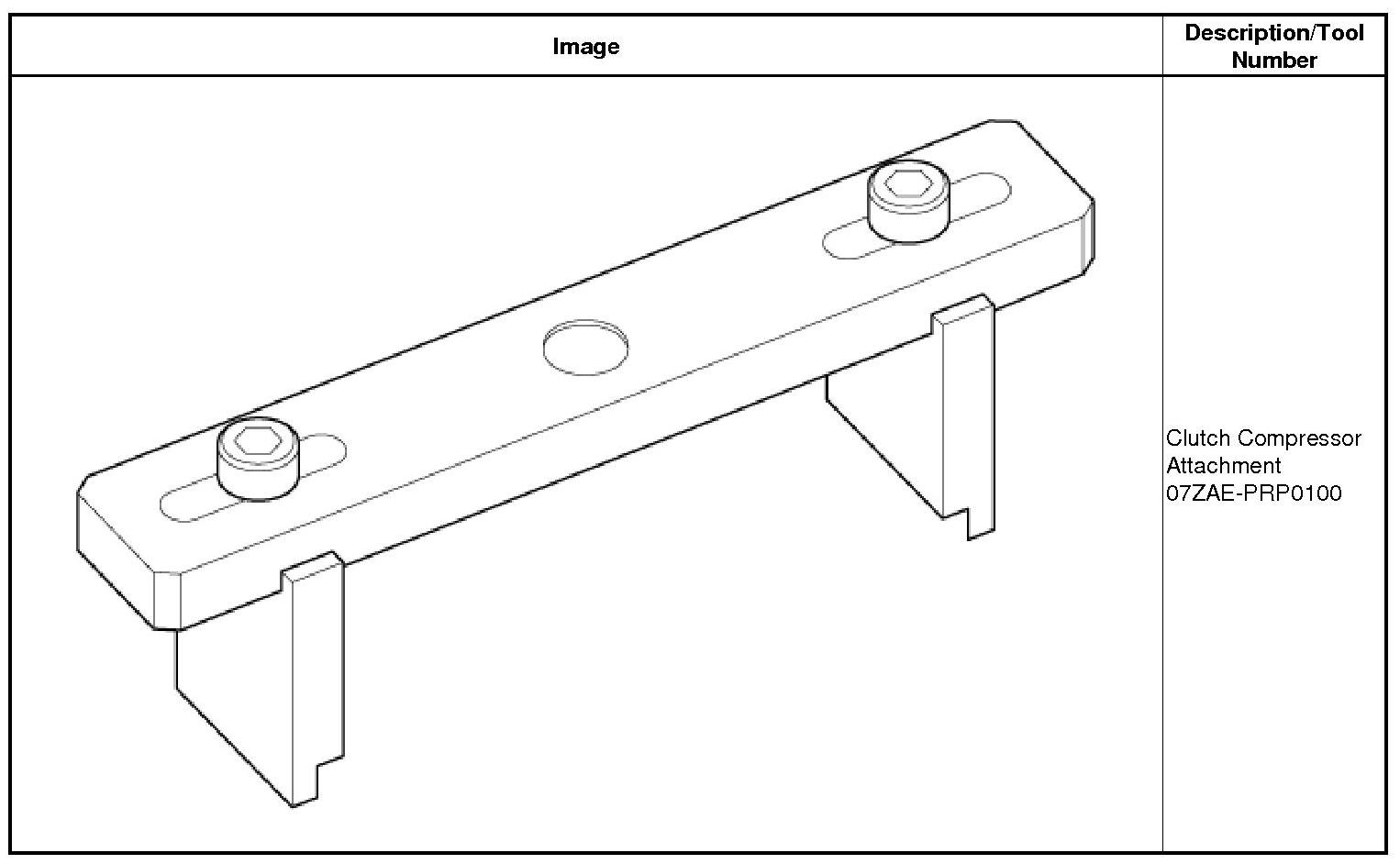
Removal
1. Flywheel Housing Assembly
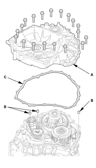
1. Remove the flywheel housing (A), the dowel pins (B), and the gasket (C).
2. CVT Differential Assembly
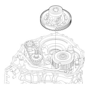
1. Remove the CVT differential assembly.
3. Lubrication Pipe
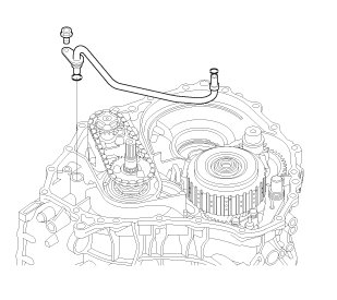
1. Remove the lubrication pipe.
4. Oil Passage Pipe
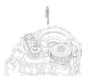
1. Remove the oil passage pipe.
5. CVTF Pump Drive Sprocket and CVTF Pump Drive Chain
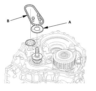
1. Remove the CVTF pump drive sprocket (A) and the CVTF pump drive chain (B).
6. CVTF Pump Drive Sprocket Hub
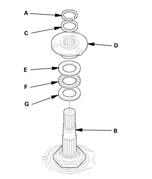
1. Remove the snap ring (A) from the input shaft (B).
2. Remove the thrust shim (C), the CVTF pump drive sprocket hub (D), the thrust washer (E), the thrust needle bearing (F), and the thrust washer (G) from the input shaft.
7. Secondary Driven Gear
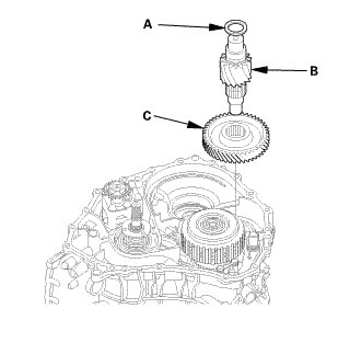
1. Remove the thrust shim (A) and the final drive shaft (B), then remove the secondary driven gear (C).
8. Start Clutch Assembly
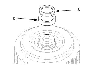
1. Remove the snap ring (A) securing the start clutch.
2. Remove the cotter retainer (B).
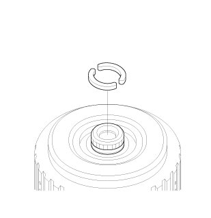
3. Remove the 25.5 mm cotters.
Start Clutch Cutaway View
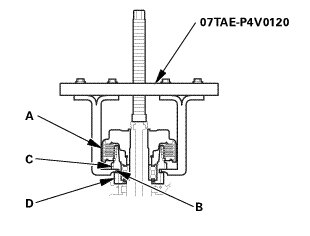
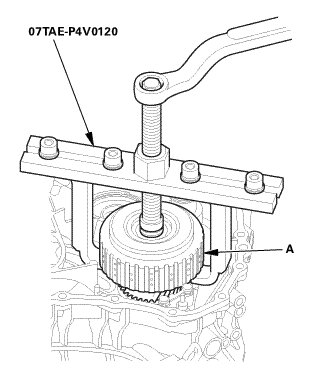
4. Set the start clutch remover on the start clutch (A), and attach the pawl (B) of the start clutch remover to between the secondary driven gear (C) and the park gear (D) securely.
NOTE:
* Do not place the pawl of the start clutch remover on the start clutch guide. If the pawl contacts the start clutch guide, the clutch guide may be damaged.
* Be sure not to allow dust and other foreign particles to enter the driven pulley shaft.
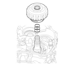
5. Remove the start clutch assembly and the secondary drive gear/park gear together from the driven pulley shaft.
9. Secondary Drive Gear
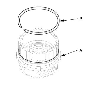
1. Remove the secondary drive gear/park gear (A) from the start clutch.
2. Remove the sealing ring (B) from the secondary drive gear/park gear.
10. Park Pawl Shaft Assembly
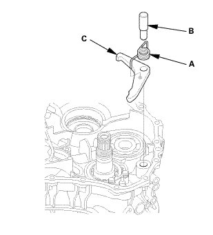
1. Remove the park pawl spring (A) and the park pawl shaft (B), then remove the park pawl (C).
11. Turn Transmission Upside Down
1. Turn the transmission upside down, and set it on a workbench to prevent damaging the input shaft and the driven pulley shaft.
12. Transmission End Cover Assembly
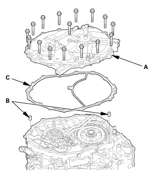
1. Remove the end cover (A), the dowel pins (B), and the gasket (C).
13. Manual Valve Body Pipe A and B
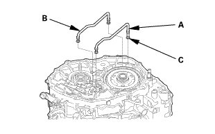
1. Remove manual valve body pipes A and B.
2. Remove the O-rings (C) from manual valve body pipes A and B.
14. CVT Planetary Carrier/Input Shaft Assembly
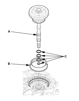
1. Remove the planetary carrier/input shaft assembly (A).
2. Remove the ring gear (B).
3. Remove the sealing rings (C) from the planetary carrier/input shaft assembly.
15. Reverse Brake Disc and Plate
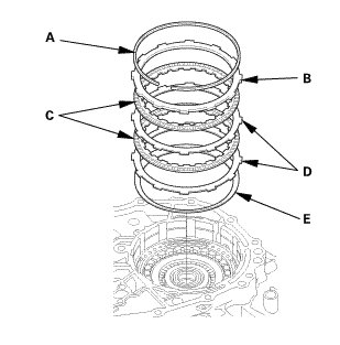
1. Remove the snap ring (A).
2. Remove the reverse brake end-plate (B), the reverse brake discs (C), the reverse brake plates (D), and the disc spring (E).
16. Forward Clutch
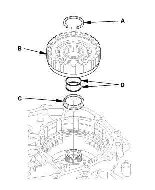
1. Remove the snap ring (A).
2. Remove the forward clutch assembly (B) and the snap ring retainer (C).
3. Remove the O-rings (D) from the drive pulley shaft.
Inspection
1. CVT Forward Clutch Clearance - Inspection
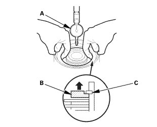
1. Set a dial indicator (A) on the clutch end-plate (B).
2. Zero the dial indicator with the clutch end-plate is lifted up to the snap ring (C).
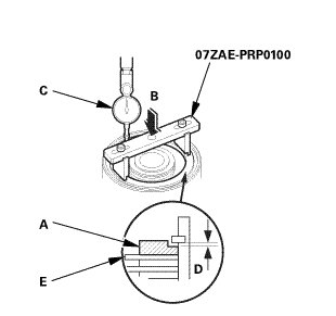
3. Release the clutch end-plate (A) to lower the clutch end-plate, then put the clutch compressor attachment on the clutch end-plate.
4. Press the clutch compressor attachment down with 39 N (4.0 kgf, 8.8 lbf) (B) using a force gauge, and read the dial indicator (C).
5. The dial indicator reads the clearance (D) between the clutch end-plate and the top disc (E). Take measurements in at least three places, and use the average as the actual clearance.

* If the clearance is out of the service limit, replace the forward clutch assembly.
Installation
1. Forward Clutch Assembly
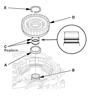
1. Install the snap ring retainer (A) over the drive pulley shaft (B).
2. Wrap the drive pulley shaft splines with tape to prevent O-ring damage. Install two new O-rings (C) in the drive pulley shaft O-ring grooves, then remove the tape.
3. Install the forward clutch assembly (D) on the drive pulley shaft.
4. Install the snap ring (E) to secure the forward clutch.
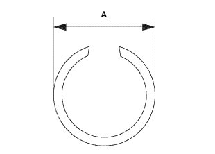
5. Check that the snap ring is seated in the snap ring groove of the drive pulley shaft, and that the snap ring outside diameter (A) is 41.4 mm (1.630 in) or less.
2. CVT Planetary Carrier/Input Shaft Assembly
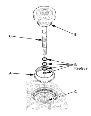
NOTE: The sealing rings of the input shaft must be replaced when disassemble the transmission.
1. Install the ring gear (A) on the forward clutch.
2. Wrap the input shaft splines with tape to prevent sealing rings damage. Install four new sealing rings (B) in the input shaft sealing ring grooves, then remove the tape.
3. Install the input shaft/planetary carrier assembly (C) through the drive pulley shaft (D) by aligning the sun gear (E) with the forward clutch discs and the planetary carrier with the reverse brake discs.
3. Manual Valve Body Pipe A and B
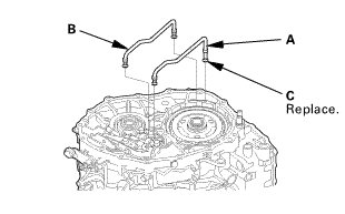
1. Install new O-rings (C) on manual valve body pipes A and B.
2. Install manual valve body pipes A and B in the intermediate housing.
4. Transmission End Cover Assembly
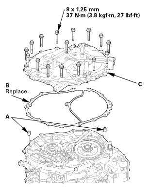
1. Install the dowel pins (A) and a new gasket (B) on the intermediate housing.
2. Install the end cover (C), and tighten them to the specified torque in a crisscross pattern in at least two or three steps.
5. Turn Transmission Upside Down
1. Turn the transmission end cover down.
6. Park Pawl Shaft Assembly
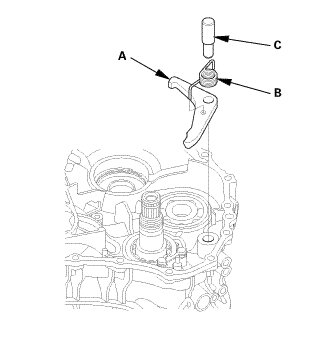
1. Install the park pawl (A), the park pawl spring (B), and the park pawl shaft (C) on the transmission housing.
2. Move the selector control lever to any position other than P.
7. Secondary Drive Gear
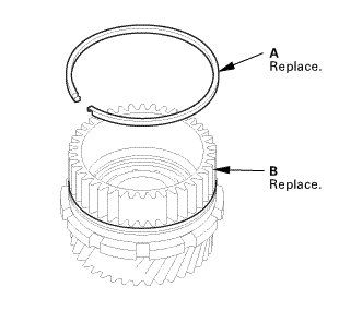
NOTE: The secondary drive gear/park gear must be replaced when disassembling the transmission.
1. Install a new sealing ring (A) on a new secondary drive gear/park gear (B).
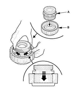
2. Insert the secondary drive gear/park gear (A) into the start clutch assembly (B). Wiggle the secondary drive gear/park gear back and forth as it goes into the start clutch discs, and push in the secondary drive gear until it bottoms out.
8. Start Clutch Assembly
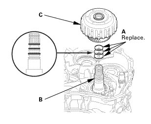
1. Use the CVTF to lubricate new O-rings (A) for the driven pulley shaft (B), then install the O-rings on the driven pulley shaft.
2. Install the start clutch assembly and the secondary drive gear/park gear (C) together on the driven pulley shaft.
NOTE: Make sure to hold the secondary drive gear engaged into the start clutch discs when you install the start clutch assembly and the secondary drive gear/park gear onto the driven pulley shaft.
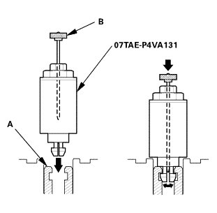
3. Seat the start clutch by aligning the tip of the start clutch installer with the driven pulley shaft hole (A) and then pushing down the handle (B).
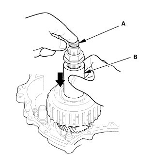
4. While holding the handle (A) down, push down the bottom part (B) of the start clutch installer until it contacts the seating surface of the start clutch.
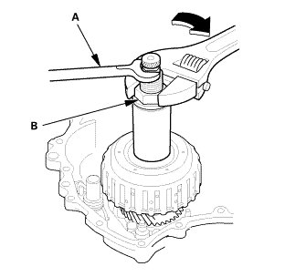
5. Hold the upper hex section of the start clutch installer with a 19 mm wrench (A), then use an adjustable wrench to tighten the lower nut (B) of the start clutch installer until the start clutch seats.
NOTE: When using the start clutch installer, hold the upper hex section and then turn the lower nut. Turning the upper hex section could damage the start clutch installer.
6. Remove the start clutch installer.
7. Reach under the start clutch to confirm that the clutch end-plate can move up and down slightly (less than 1.0 mm (0.039 in)).
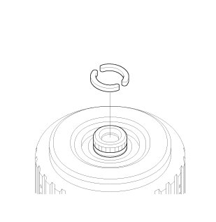
8. Install the 25.5 mm cotters to the cotter groove on the driven pulley shaft.
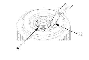
9. Measure the clearance between the cotters and the start clutch guide (A) using a feeler gauge (B). Take measurements in at least three places, and use the average as the actual clearance.

* If the clearance is out of the standard, remove the cotters, and measure its thickness. Select new 25.5 mm cotters from the following table and install it. Then recheck that the clearance is within the standard.

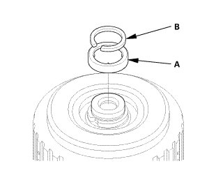
10. Install the cotter retainer (A) and the snap ring (B) to the driven pulley shaft.
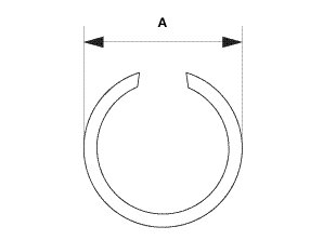
11. Check that the snap ring is seated in the snap ring groove of the driven pulley shaft, and that the snap ring outside diameter (A) is 33.9 mm (1.335 in) or less.
9. CVTF Pump Drive Sprocket Hub
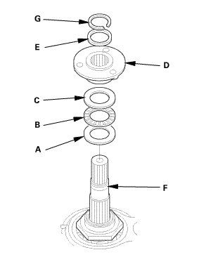
1. Install the thrust washer (A), the thrust needle bearing (B), the thrust washer (C), the CVTF pump drive sprocket hub (D), and the 22 x 28 mm thrust shim (E) on the input shaft (F).
2. Install the snap ring (G) to the input shaft.
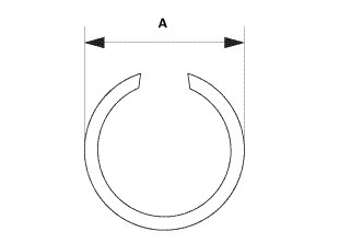
3. Check that the snap ring is seated in the snap ring groove of the input shaft, and that the snap ring outside diameter (A) is 26.3 mm (1.035 in) or less.
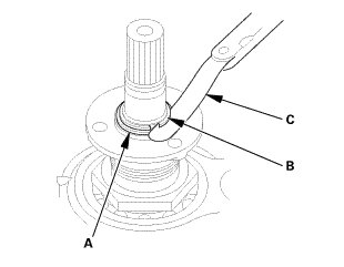
4. Measure the clearance between the 22 x 28 mm thrust shim (A) and the snap ring (B) using a feeler gauge (C). Take measurements in at least three places, and use the average as the actual clearance.

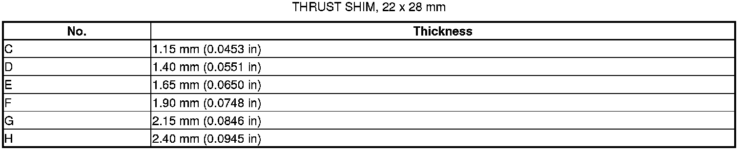
* If the clearance is out of the standard, remove the 22 x 28 mm thrust shim, and measure its thickness. Select a new 22 x 28 mm thrust shim from the following table and install it, then recheck that the clearance is within the standard.
* If the 22 x 28 mm thrust shim is replaced, install the snap ring, and check that the snap ring outside diameter is within the tolerance.
10. Secondary Driven Gear
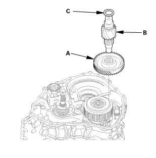
1. Place the secondary driven gear (A) on the transmission housing by aligning it with the secondary drive gear, and install the final drive shaft (B) through the secondary driven gear into the transmission housing.
2. Install the 25 x 35 mm thrust shim (C) on the final drive shaft.
11. CVTF Pump Drive Sprocket and CVTF Pump Drive Chain
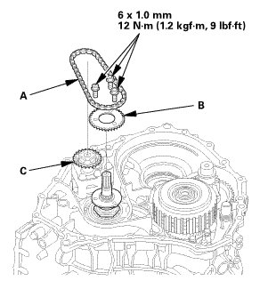
1. Install the CVTF pump drive chain (A) by aligning sprocket tooth on the CVTF pump drive sprocket (B) and the CVTF pump driven sprocket (C).
2. Position the CVTF pump drive sprocket and the CVTF pump drive chain together on the CVTF pump drive sprocket hub.
3. Secure the CVTF pump drive sprocket with the bolts.
12. Oil Passage Pipe
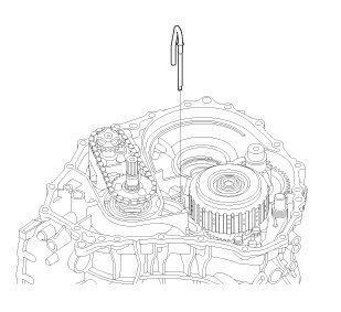
1. Install the oil passage pipe.
13. Lubrication Pipe
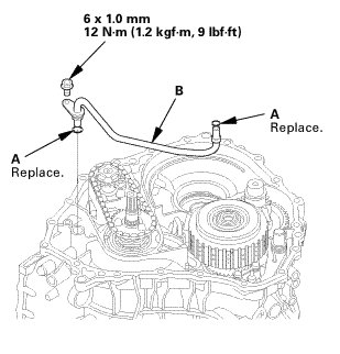
1. Install new O-rings (A) on the lubrication pipe (B).
2. Install the lubrication pipe.
14. CVT Differential Assembly
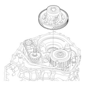
1. Install the differential assembly onto the transmission housing.
15. Flywheel Housing Assembly
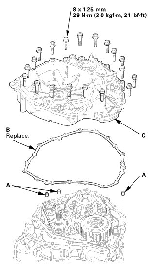
1. Install the dowel pins (A) and a new gasket (B) on the transmission housing.
2. Install the flywheel housing (C) on the transmission housing, and tighten them to the specified torque in a crisscross pattern in at least two or three steps.