Part Two
Valve Seat Reconditioning
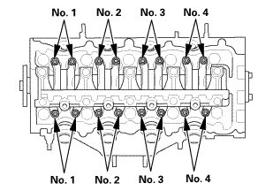
18. Valve Clearance Adjustment
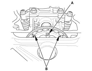
1. Set the No. 1 piston at top dead center (TDC). The "UP" mark (A) on the camshaft sprocket should be at the top, and the TDC grooves (B) on the camshaft sprocket should line up with the top edge of the head.
2. Select the correct feeler gauge for the valve clearance you are going to check.

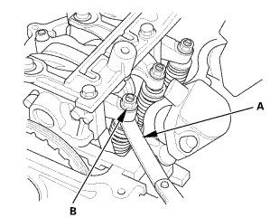
3. Insert the feeler gauge (A) between the adjusting screw (B) and the end of the valve stem on the No. 1 cylinder, and slide it back and forth; you should feel a slight amount of drag.
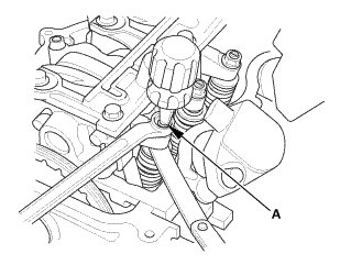
4. If you feel too much or too little drag, loosen the locknut, and turn the adjusting screw (A) until the drag on the feeler gauge is correct.
5. Tighten the locknut to the specified torque, and recheck the clearance. Repeat the adjustment if necessary.
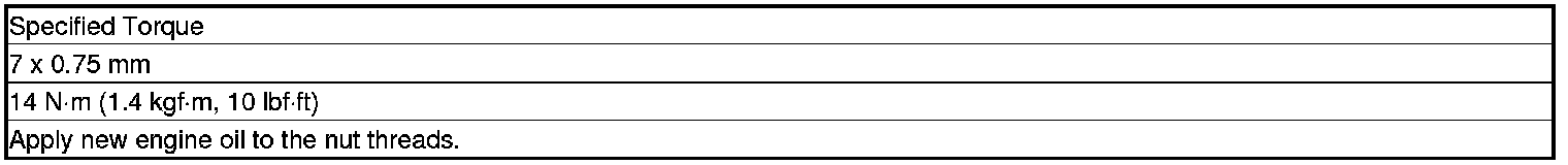
6. Rotate the crankshaft clockwise. Align the No. 3 piston TDC groove (A) on the camshaft sprocket with the top edge of the head.
7. Check and, if necessary, adjust the valve clearance on the No. 3 cylinder.
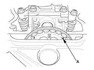
8. Rotate the crankshaft clockwise. Align the No. 4 piston TDC groove (A) on the camshaft sprocket with the top edge of the head.
9. Check and, if necessary, adjust the valve clearance on the No. 4 cylinder.
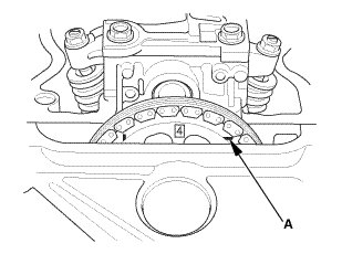
10. Rotate the crankshaft clockwise. Align the No. 2 piston TDC groove (A) on the camshaft sprocket with the top edge of the head.
11. Check and, if necessary, adjust the valve clearance on the No. 2 cylinder.
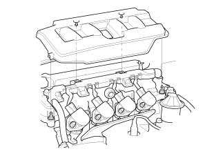
19. Cylinder Head Cover and/or Packing
1. Thoroughly clean the head cover gasket and the groove.
NOTE: Check and, if necessary, replace the head cover gasket.
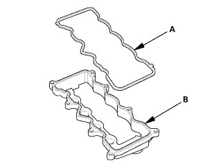
2. Install the head cover gasket (A) in the groove of the cylinder head cover (B).
3. Make sure the head cover gasket is seated securely.
4. Clean the head cover contacting surfaces with a shop towel.
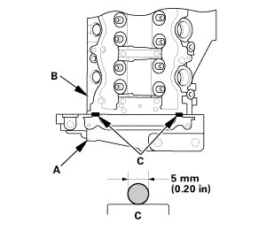
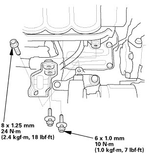
5. Remove the old liquid gasket from the top edge matting surfaces of the oil pump (A) and cylinder head (B).
6. Apply liquid gasket (P/N 08718-0004 or 08718-0009) to the chain case contact areas. Install the component within 5 minutes of applying the liquid gasket.
NOTE:
* Apply a 5 mm (0.20 in) diameter bead of liquid gasket to the mating surfaces (C).
* If too much time has passed after applying the liquid gasket, remove the old liquid gasket and residue, then reapply new liquid gasket.
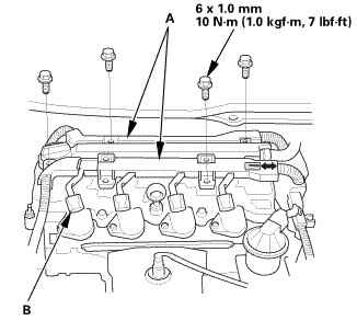
7. Install the cylinder head cover.
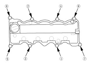
8. Tighten the bolts in two steps. In the final step, torque all bolts in sequence to 10 Nm (1.0 kgfm, 7 lbfft).
NOTE:
* Wait at least 30 minutes before filling the engine with oil.
* Do not run the engine for at least 3 hours after installing the head cover.
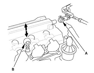
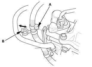
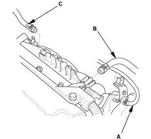
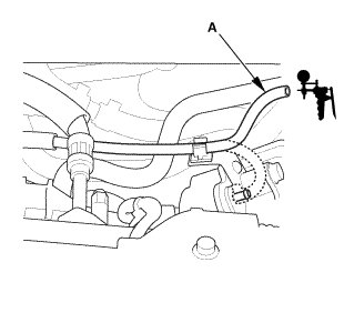
9. Connect the breather hose (A).
10. Install the dipstick (B).
20. Auto Tensioner Assembly
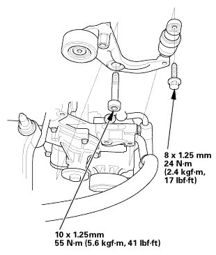
1. Install the drive belt auto-tensioner.
21. Water Pump Pulley
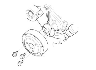
1. Install the water pump pulley.
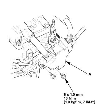
22. Alternator
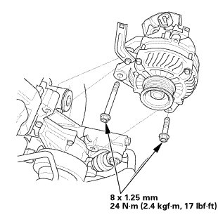
1. Install the alternator.
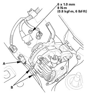
2. Connect the connector and the cable. Make sure the crimped side of the ring terminal faces away from the alternator when you connect it.
3. Install the harness connector (A) and the harness clamps (B).
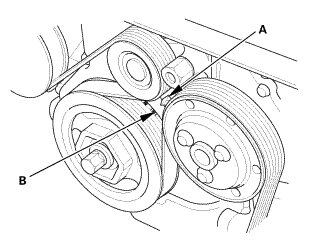
23. Drive Belt
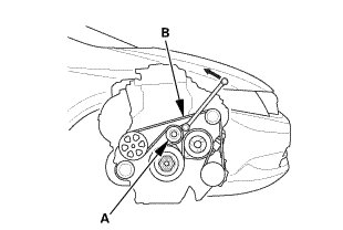
1. Move the auto-tensioner (A) counterclockwise.
2. Install the drive belt (B).
24. Water Pump Pulley Mounting Bolt - Tighten
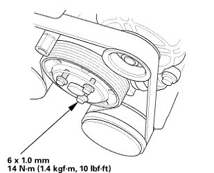
1. Tighten the water pump pulley mounting bolts.
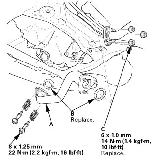
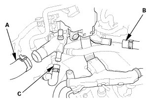
25. Thermostat Housing (Natural Gas Model)
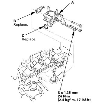
1. Install the thermostat housing (A), using a new gasket (B) and new O-ring (C).
26. Thermostat Housing Peripheral Assembly (Natural Gas Model)
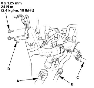
1. Connect the lower radiator hose (A), the water bypass hose (B), and the heater hose (C).
2. Install the harness bracket (D).
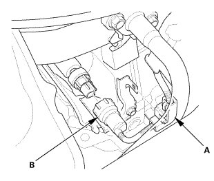
3. Install the harness clamp (A).
4. Connect the connector (B).
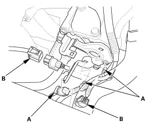
5. Install the harness clamps (A).
6. Connect the connectors (B).
27. Catalytic Converter (Natural Gas Model)
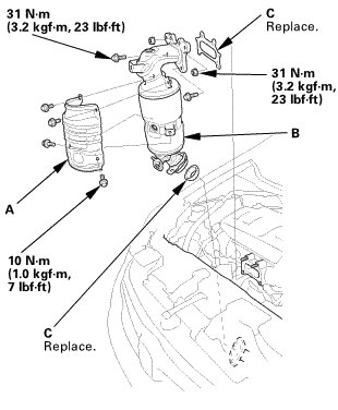
1. Install the catalytic converter cover (A).
2. Install the catalytic converter (B) with new gaskets (C).
28. Exhaust Pipe A
1. Install exhaust pipe A. Use new gaskets (B) and new self-locking nuts (C).
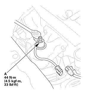
29. Secondary HO2S
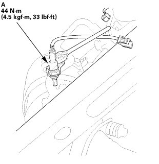
1. Install secondary HO2S (A).
2. Connect the connector.
30. Engine Undercover
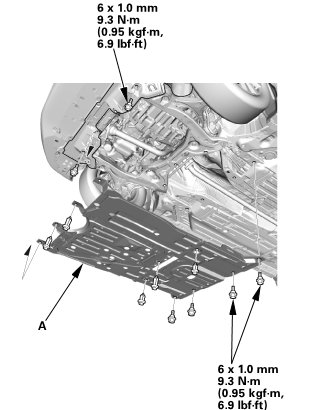
1. Install the engine undercover (A).
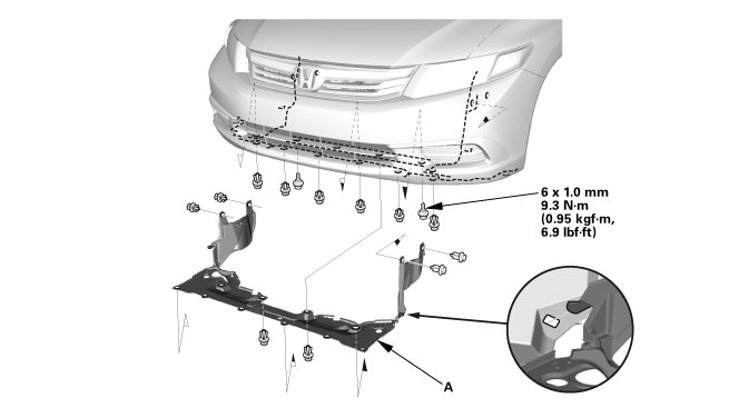
31. Splash Shield
1. Install the splash shield (A).
32. Exhaust Chamber Cover (Natural Gas Model)
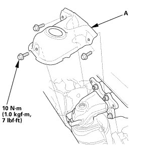
1. Install the exhaust chamber cover (A).
33. A/F Sensor (Sensor 1)
1. Install the A/F sensor (A).
2. Connect the connector.
34. Ignition Coil
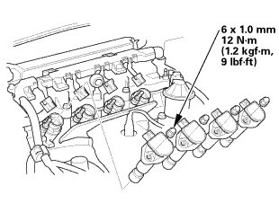
1. Install the ignition coils.
35. Cylinder Head Peripheral Assembly
1. Connect the upper radiator hose (A), the heater hose (B), and the water bypass hose (C).
2. Install the harness holder (A) to the cylinder head.
3. Install the harness clamps (A).
4. Connect the PCV hose to the clamp (B).
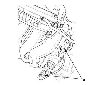
5. Install the harness holders (A).
6. Connect the connectors (B).
36. Intake Manifold Assembly (Natural Gas Model)
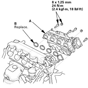
1. Install the intake manifold assembly (A) with new gaskets (B).
2. Tighten the bolts/nuts in a crisscross pattern in three steps, beginning with the inner bolt.
3. Install the connectors (A).
4. Connect the harness clamps.
5. Install the intake manifold bracket.
6. Install the heater hose clamp bracket.
7. Connect the EVAP canister hose (A), the brake booster vacuum hose (B), and the PCV hose (C).
37. Throttle Body - Install (Natural Gas Model)
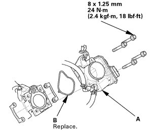
1. Install the throttle body (A) with new gasket (B).
38. Intake Air Duct
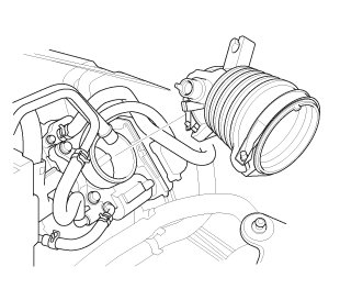
1. Install the intake air duct.
39. Fuel Feed Hose (Natural Gas Model)
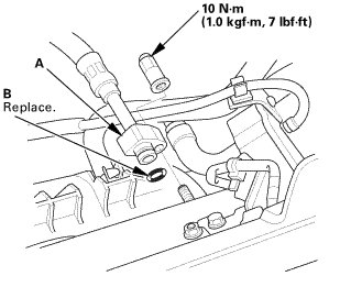
1. Connect the fuel feed hose (A) with a new O-ring (B).
40. Under Cowl Panel
1. Install the under cowl panel (A).
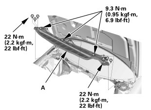
41. Center Cowl Cover
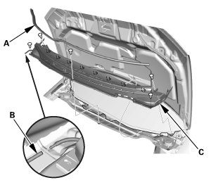
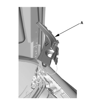
1. If necessary, install the hood rear seal (A).
2. Connect the windshield washer tube (B).
3. Install the center cowl cover (C).
42. Both Side Cowl Covers
1. Install the side cowl cover (A).
2. The left side is shown; repeat on the right side.
43. Wiper Arm Assembly
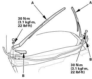
NOTE: Set the wiper arms to the auto-stop position before installation.
1. Install the wiper arms (A).
2. Install the cowl top wiper covers (B).
44. Air Cleaner
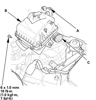
1. Install the harness clamp (A).
2. Install the air cleaner (B).
3. Connect the intake air duct (C).
45. Intake Air Pipe
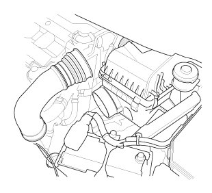
1. Install the intake air pipe.
46. Engine Cover
1. Install the engine cover.
47. Battery
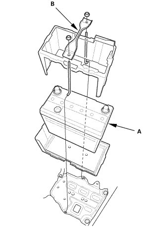
1. Install the battery (A) and the battery setting plate (B).
NOTE: Do not deform the battery setting plate by over-tightening the nuts.
48. Battery Terminal - Reconnection
NOTE: If the battery performs abnormally, test the battery.
1. Clean the battery terminals.
2. Connect the positive cable (A) to the battery.
NOTE: Always connect the positive side first.
3. Connect the negative cable and battery sensor (B) to the battery.
4. Apply multipurpose grease to the terminals to prevent corrosion.
49. Manual Shut-off Valve - Open (Natural Gas Model)
1. Open the manual shut-off valve (A).
50. Fuel Supply System Leak - Inspection (Natural Gas Model)
Check for a gas leak if there is an odor coming from the vehicle. Compressed natural gas (CNG) can only be smelled, not seen.
1. Open the hood and the fuel fill door.
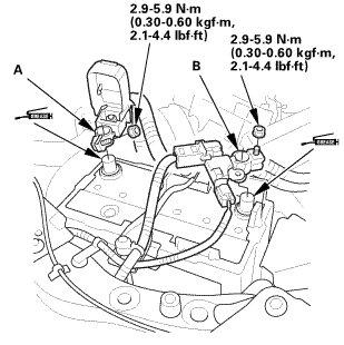
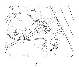
2. Connect a vacuum pump/gauge, 0-30 inHg, to the hose (A) from fuel pressure regulator P1, and apply 67.7 kPa (20.0 inHg, 508 mmHg) of vacuum.
3. If fuel pressure regulator P2 does not hold vacuum, replace it before continuing to the next step.
4. Inspect the fuel lines and hoses under the hood for kinks, abrasion, and other signs of damage.
5. With the manual shut-off valve open, turn the ignition switch to ON (II), but do not start the engine.
6. After the fuel pressure regulator shut-off solenoid valve/fuel tank internal solenoid valve operates for about 2 seconds, the fuel pressure in the fuel lines rises.
7. Turn the ignition switch to LOCK (0).
8. Repeat this two or three times.
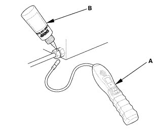
9. Within 1 minute, check for any damaged lines with a leak detector (A) (Snap-on Combustible Gas Leak Detector or Snoop Liquid Leak Detector (B)).
10. If no damage was noticed during the inspection, turn the ignition switch to ON (II) for 2 seconds, then turn the ignition switch to LOCK (0).
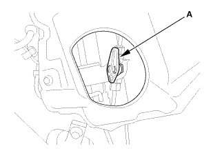
11. Within 1 minute, check for a leak at the vent hose outlet inside the fuel pipe protector (A).
12. If you detect a leak, remove the vent hose, and check the fuel lines and fittings at the in-tank solenoid valve and the join block with a leak detector.
13. If you cannot find the leak, raise the vehicle on a lift, remove the under-floor cover.
14. Inspect all the fuel lines under the vehicle, visually, and with a leak detector.
15. If you still cannot find the leak, remove the rear seat, then check all fuel lines and fittings at the fuel tank and the fuel joint block.
51. Radiator Coolant - Replacement (Natural Gas Model)
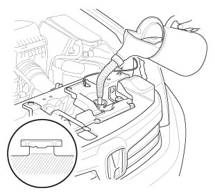
1. Pour Honda Long Life Antifreeze/Coolant Type 2 into the radiator up to the base of the filler neck.
NOTE:
* Always use Honda Long Life Antifreeze/Coolant Type 2. Using a non-Honda coolant can result in corrosion, causing the cooling system to malfunction or fail.
* Honda Long Life Antifreeze/Coolant Type 2 is a mixture of 50 % antifreeze and 50 % water. Do not add water.


52. Tire and Wheel-Installation, Front Right
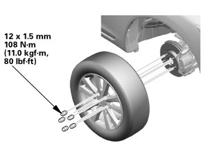
1. Install the right front wheel.
NOTE: Before installing the wheel, clean the mating surfaces between the brake disc and the inside of the wheel.
53. Warm Up The Engine
Start the engine. Hold the engine speed at 3,000 rpm without load (A/T in P or N, M/T in neutral) until the radiator fan comes on, then let it idle.
54. HDS DLC - Connection
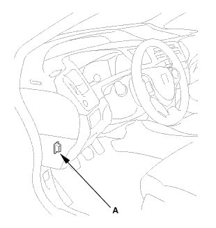
1. Connect the HDS to the data link connector (DLC) (A) located under the driver's side of the dashboard.
2. Turn the ignition switch to ON (II).
3. Make sure the HDS communicates with the vehicle. If it does not communicate, go to the DLC circuit troubleshooting.
55. Idle Speed - Inspection (Natural Gas Model)
NOTE:
* Before checking the idle speed, check these items:
- The malfunction indicator lamp (MIL) has not been reported on, and there are no DTCs.
- Ignition timing
- Spark plugs
- Air cleaner
- PCV system
* Apply the parking brake, and make sure the headlights are off.
1. Check the idle speed without load conditions: headlights, blower fan, radiator fan, and air conditioner off.
Idle speed should be: 670±50 rpm (in P or N)
2. Let the engine idle for 1 minute with high electric load (A/C on, temperature set to max cool, blower fan on high, headlights on high beam).
Idle speed should be: 710±50 rpm (in P or N)
NOTE: If the idle speed is not within specification, do the PCM idle learn procedure. If the idle speed is still not within specification, go to the symptom troubleshooting.
56. CKP Pattern Clear/CKP Pattern Learn
1. Select CRANK PATTERN in the ADJUSTMENT MENU with the HDS.
2. Select CRANK PATTERN CLEAR, and clear the CKP pattern.
3. Select CRANK PATTERN LEARNING with the HDS, and follow the screen prompts.
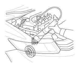
57. Ignition Timing - Inspection
1. Jump the SCS line with the HDS.
2. Connect the timing light to the No. 1 ignition coil harness.
3. Aim the light toward the pointer (A) on the cam chain case. Check the ignition timing under a no load condition (headlights, blower fan, rear window defogger, and air conditioner are turned off).

4. If the ignition timing differs from the specification, check the camshaft timing. If the camshaft timing is OK, update the ECM/PCM if it does not have the latest software, or substitute a known-good ECM/PCM, then recheck. If the system works properly, and the ECM/PCM was substituted, replace the original ECM/PCM.
5. Disconnect the HDS and the timing light.
58. Maintenance Minder Reset
1. After doing all procedures, select the individual maintenance item you wish to reset with the HDS (See the Maintenance Minder General Information).