Part 1
Navigation System Diagnostic Mode
Start-Up procedure and Diagnosis Menu
NOTE: Check the vehicle battery condition first Battery Test.
There are two ways to enter the diagnostic mode:
Mode 1:
Start the vehicle, and at the disclaimer screen, press and hold the 3 buttons MENU, MAP/GUIDE, and CANCEL, for about 5 seconds. The display screen goes directly to the Select Diagnosis Items menu.
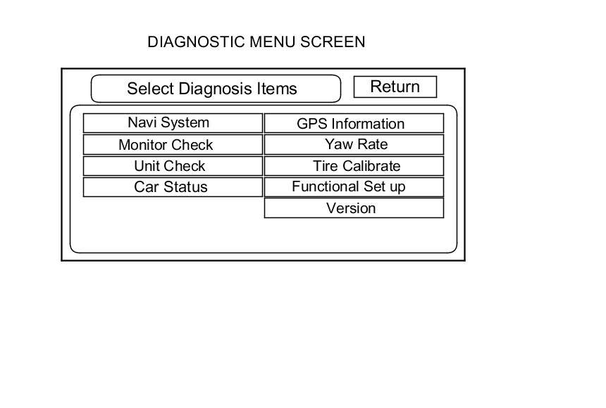
After the display changes to the Diagnostic items menu, select the item you want to check, and the diagnostic will start. To return to the previous screen, select Return.
- Navi System (Link)
- Monitor Check
- Unit Check
- Car Status
- F-CAN (System link)
- GPS Information
- Yaw Rate
- Tire Calibrate
- Functional Setup
- Version
Mode 2:
Start the vehicle. When the globe screen appears, connect the SCS service connector Forced Starting Of The Navigation Unit (With Navigation) to the navigation service connector located in the trunk. The screen changes to the diagnostic menu screen.
NOTE: When finished troubleshooting, make sure to remove the SCS service connector.
Factory Diagnostic Screen In Line Diag
NOTE: If the vehicle left the factory in the factory diagnosis mode, you will see this screen every time you turn on the ignition. You may also see this screen if you recently replaced the navigation unit.
When a navigation unit is powered up for the first time at the factory, the factory diagnosis screen (In Line Diag) appears. Normally the factory performs the steps necessary to verify proper operation and terminate the factory diagnostic.
Until the proper confirmation sequence is done, the screen appears every time the vehicle is started.
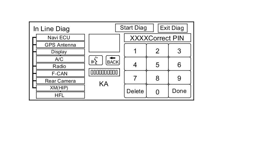
Follow the steps below to prevent the screen from showing up in the future:
- Press and hold the buttons MENU, the MAP/GUIDE, and the CANCEL buttons for about 3 seconds (the Select Diagnosis items screen appears).
- Press the hold the MAP/GUIDE button for 5-10 seconds. A screen with a Complete button, appears.
- Touch Complete, and then the Return button (the system may re-boot).
- Restart the vehicle, and confirm normal operation by completing the "PDI of the Navigation System" Service Bulletin.
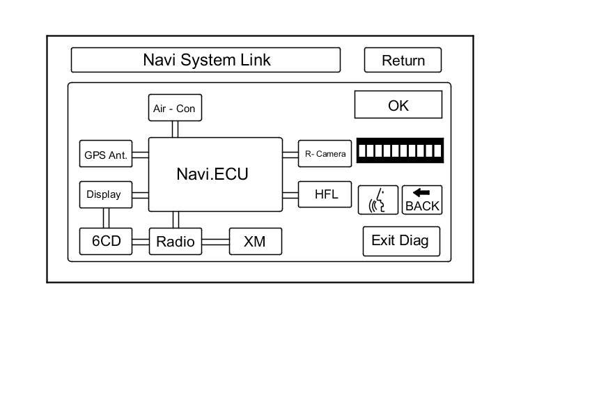
Navi System Link
- This diagnostic tests the wires connecting the navigation components. Ensure that the ignition switch is in the ON (II) position. When the diagnostic begins, you hear a long sound. The system is in a Detecting mode, and is waiting for all items in white to be tested. This includes the voice control switch (navigation TALK/BACK buttons), and microphone. Press the navigation TALK button on the steering wheel, and in a normal voice, say "testing". The talk indicator on the screen should turn green, and the voice level indicator should move to at least the 6th bar to pass. Next, press the navigation BACK button. The Cancel indicator should turn green.
- If all of the communication lines connecting the system components, and the navigation TALK/BACK buttons/microphone check out OK (all block diagram items green), then the OK indicator turns green.
- If there is a problem with the system, the faulty system component item turns red, and the screen shows NG in red. Use the troubleshooting index and other diagnostic screens to help locate the problem.
- The indication on the screen may not change until you cycle the ignition switch. After repairing the affected cable or system, repeat this diagnostic.
NOTE: Green boxes and green OK indicate that the communications lines (wires) are intact. This diagnostic does not necessarily imply that the individual components are functioning properly. For instance, the GPS antenna wire may be crushed, but still show as green. A road test, or other diagnostic may be necessary to find the problem. The rearview camera feature is optional. If the camera is not installed, the rear camera icon is yellow/orange. When the camera is installed the icon is green. If the icon is not green with the rearview camera installed, check for opens or shorts in the rearview camera cable.
- Select Return to return to the Diagnostic Menu or the Exit Diag button to exit.
NOTE:
- The Mic Level indicator must reach the 6th bar or greater to pass the test.
- If the XM link is red or flashing red, go to audio system symptom troubleshooting, or see XM diagnostic screen.
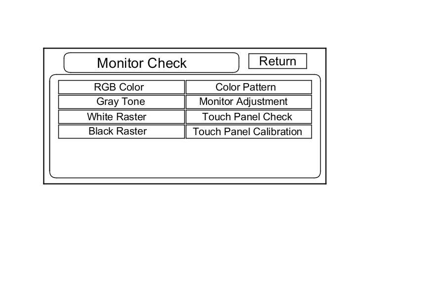
Monitor Check
Overview of navigation display unit
- The illumination input from the gauge brightness control provides back lighting for the buttons surrounding the screen and the illumination ON and OFF signal for the display back lighting.
- The illumination cancel signal is provided by the gauge via B-CAN to the HVAC unit, then to the navigation unit via the UART bus.
- The navigation display communicates with the navigation unit over its own GA-Net bus. Information is sent to the navigation unit whenever the user activates the touch screen, or buttons. Information sent by the navigation unit to the navigation display includes commands to control the LCD back light.
- The security system protects the navigation display by daisy-chaining the security signal through it, and then passing the signal to the audio unit.
These screens allow you to troubleshoot the navigation display unit. Select the item you want to troubleshoot, and follow the diagnostic instructions.
- RGB Color
- Gray Tone
- White Raster
- Black Raster
- Color Pattern
- Monitor Adjustment
- Touch Panel Check
- Touch Panel Calibration
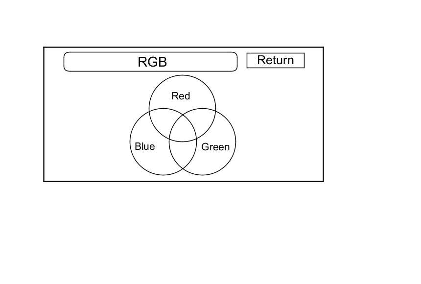
RGB Color
This screen verifies that the navigation display is receiving the video (R, G, B and Composite sync) signals properly. The three primary colors should all appear without distortion. The combination of all three should produce a central white section. If any of the colors are missing, troubleshoot for the color signal Symptom Troubleshooting. If the picture has lines in it, or scrolls horizontally or vertically, troubleshoot for a Composite sync problem Symptom Troubleshooting.
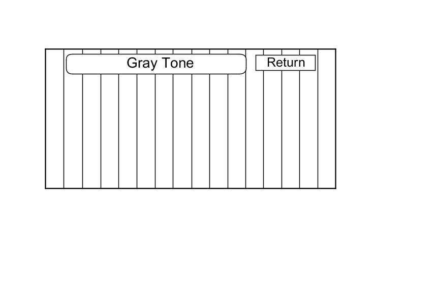
Gray Tone
This screen diagnoses problems with contrast. You should be able to see the changes from bar to bar across the scale. It is normal for the two bars on either side to appear the same. If you can't see changes from bar to bar, replace the navigation display unit Service and Repair.
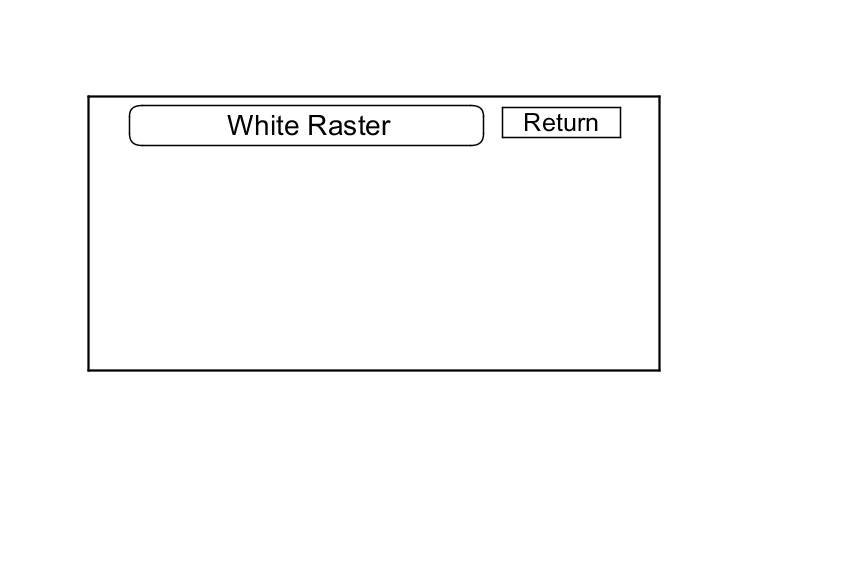
White Raster
This diagnostic screen checks for pixels that may be dead (off). The entire display must be white. If there are dead pixels, replace the navigation display unit Service and Repair.
Black Raster
This diagnostic screen checks for pixels that may be stuck on. The entire display must be black. If pixels are stuck on, replace the navigation display unit Service and Repair.
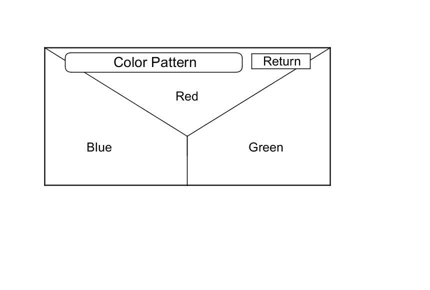
Color Pattern
The diagnostic screen shows the colors being used for the map and menu screens. This is for factory use only. To check the color signal use the RGB. Color diagnostic found under the Monitor Check.
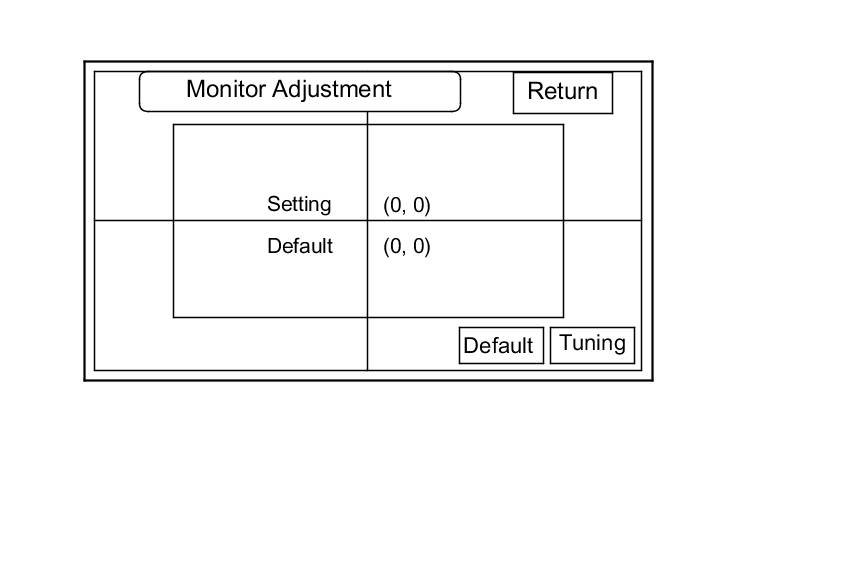
Monitor Adjustment
This allows you to center the navigation display. This is for factory use. Use this procedure only if you are directed by the factory, or other service information like a service bulletin, use the joystick to move the picture up/down or left/right. It is unlikely that you will ever need to adjust the monitor position. The Default button will reset the display position to factory specifications. The factory default is (0, 0).
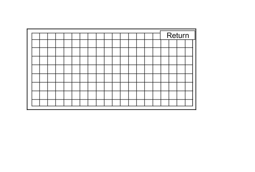
Touch Panel Check
The panel touch sensing system consists of a touch sensitive resistive membrane covering the display. Contrary to other systems using infrared beams, the screen has to be physically touched to make it work. The display has the capability of an almost infinite number of touch locations. However, to be compatible with earlier systems, the software only senses the locations shown on the diagnostic screen below. Every possible touch button position is shown on this diagnostic screen. Touching one of these areas should cause its color to reverse, and sound a beep. If the touch locations are off slightly (by less than one touch location), use the Touch Panel Calibration diagnosis to re-align the touch zones with the screen image. If any areas of the screen either does not respond, or respond at some other location when touched, then replace the navigation display unit Service and Repair.
NOTE: Unlike earlier screens that used infrared sensors, direct sunlight does not affect this test.
Touch Panel Calibration
The display screen uses a touch sensitive membrane instead of fixed infrared beams. This means that every location of the entire surface of the display is touch sensitive.
For the display to be compatible with earlier navigation systems, the system software creates touch zones emulating the touch switches created by the intersections of 20 vertical and 10 horizontal infrared beams. This diagnostic allows alignment of these artificially created zones with the location of the button images on the screen.
This should never need adjustment, and it is used only by the factory to adjust the touch locations for parallax (the touch locations appear different when viewed at an angle). If you are directed to make an adjustment by the factory or other service information, follow this procedure:
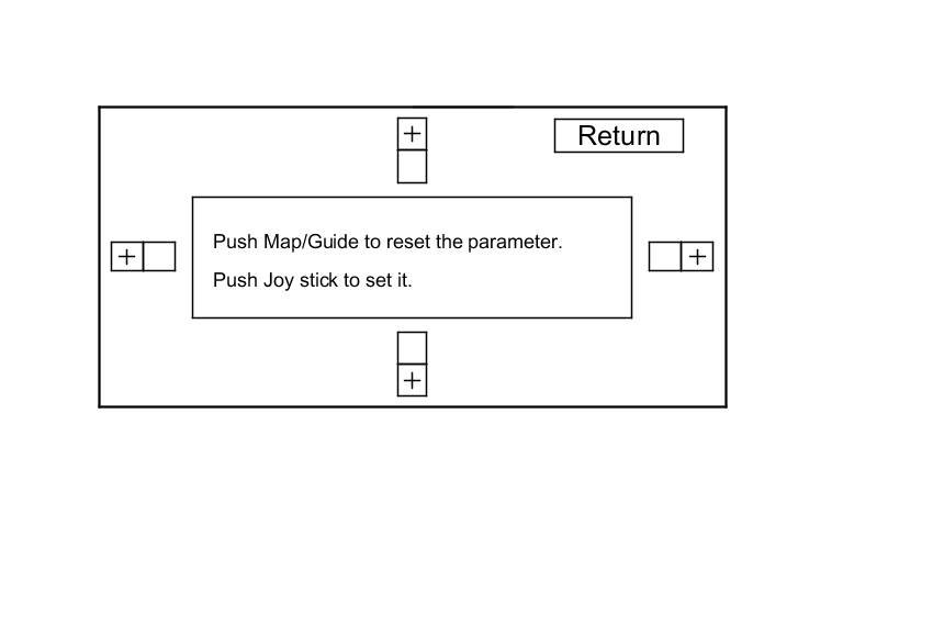
- The screen consists of four test areas consisting of a + button and an adjacent box with a black border. Touch the four + buttons to verify alignment. If, when you touch a + button, the adjacent box becomes yellow, then do the following. Continue to hold the + button, and simultaneously move the joystick to shift the screen slightly from side to side, or up and down. The adjustment is complete when you can touch all four + boxes and none of the adjacent boxes becomes yellow.
- To store any changes you make, push in the joystick.
- To reset the touch zones to the factory default, touch the Map/Guide button.
- Press Return to exit the diagnostic.