Inspection Procedure
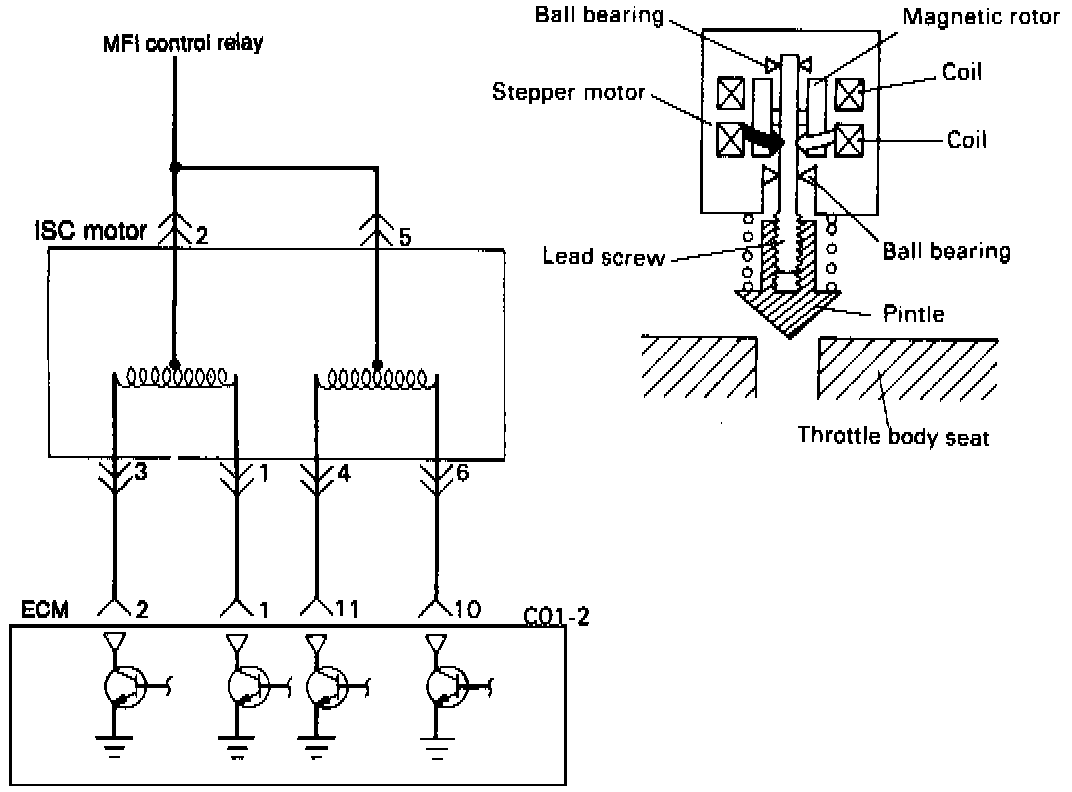
CIRCUIT DIAGRAM
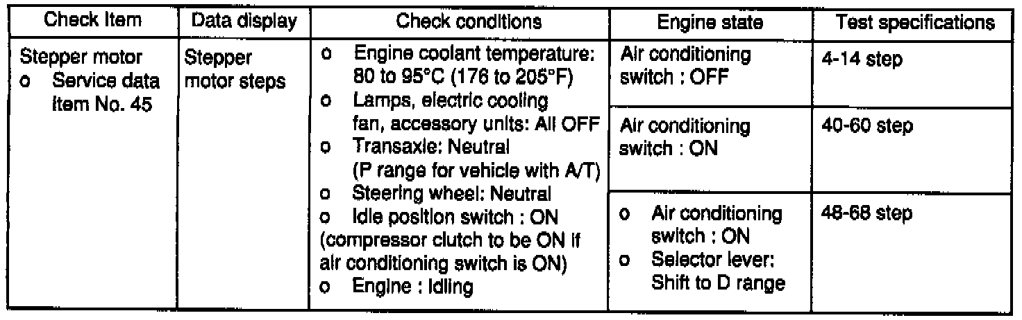
INSPECTION USING SCAN TOOL
COMPONENT TEST PROCEDURE
Operation Sound Check
1. Check for the sound of the stepper motor after the ignition is switched ON (but without starting the motor).
2. It the operation sound cannot be heard, check the stepper motor's circuit.
3. If the circuit is normal, then the problem may be the stepper motor or the ECM
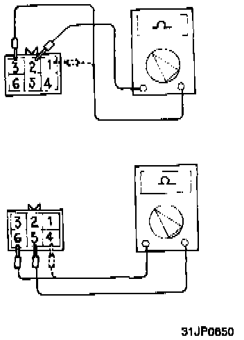
Resistance Measurement between terminals Measure the resistance between the respective terminals.
Standard value:
Terminals 2-3 and 1: 28-33 Ohms at 2O°C (68°F)
Terminals 5-4 and 6: 28-33 Ohms at 2O°C (68°F)

Operation Check
Apply voltage as follows and check whether or not stepper motor movement occurs.
- Connect the power supply (approx. 6V) terminal (+) to terminals 2 and 5 of the connector.
- Connect the power supply (-) terminal to terminals 3 and 4
- Connect the power supply (-) terminal to terminals 3 and 4
- Connect the power supply (-) terminal to terminals 3 and 6
- Connect the power supply (-) terminal to terminals 1 and 6
- Connect the power supply (-) terminal to terminals 1 and 4.
- Repeat the tests in sequence from (6) to (1).
- If vibration is detected, the stepper motor can be considered to be normal.