Reassembly
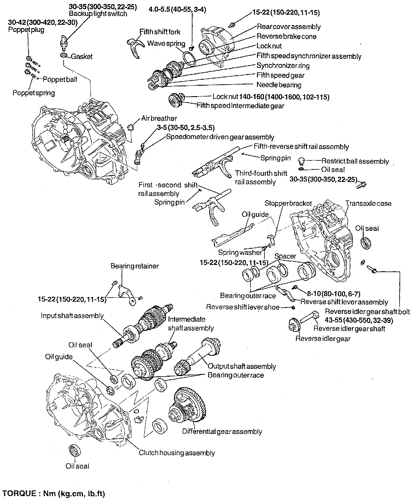
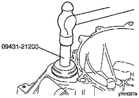
1. Install the drive shaft oil seal using the special tool (09431- 21200) or equivalent.
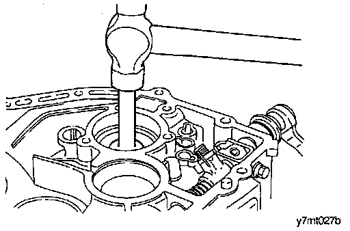
2. Install the input shaft front oil seal using the special tool (09431 - 21000) or equivalent.
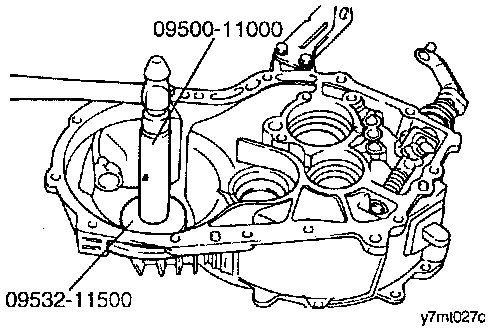
3. Install the differential gear bearing outer race and spacer using the special tools (09500 - 11000, 09532 - 11500) or equivalents.
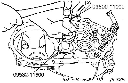
4. Install the output shaft bearing outer race and spacer using the special tool (09500 - 11000, 09532 - 11500) or equivalents.
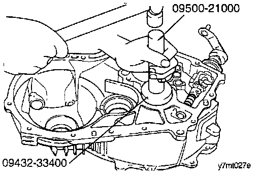
5. Install the oil guide and intermediate shaft bearing outer race and spacer using the special tools (09500 - 21000, 09432 - 33400) or equivalents.
6. Install the differential gear assembly and output shaft assembly.
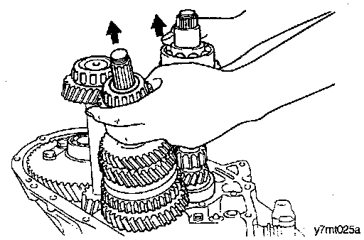
7. While lifting up the input shaft assembly, install it simultaneously with the intermediate shaft assembly.
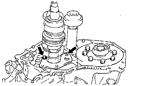
8. Install the retainer.
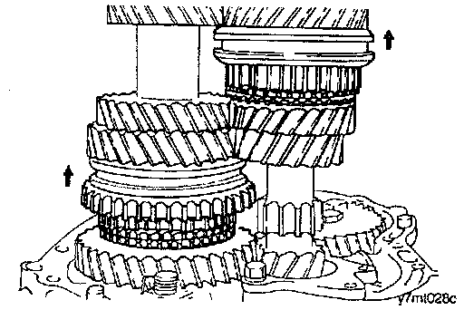
9. Reassembly of shift rail assembly, as follows:
a. Set the first-second speed shift sleeve at 2nd speed.
b. Set the third-fourth speed shift sleeve at 4th speed.
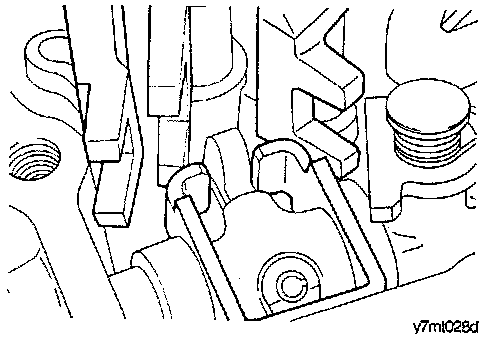
c. Install the first-second shift rail and fork assembly with the select lever pulled to fifth-reverse shift rail side.
d. Install the third-fourth/fifth-reverse shift rail and fork assembly together with the select lever fully pushed to first-second rail side.
e. Turn the shift rail to engage the shift lug.
10. Reassembly of spring pin, as follows:
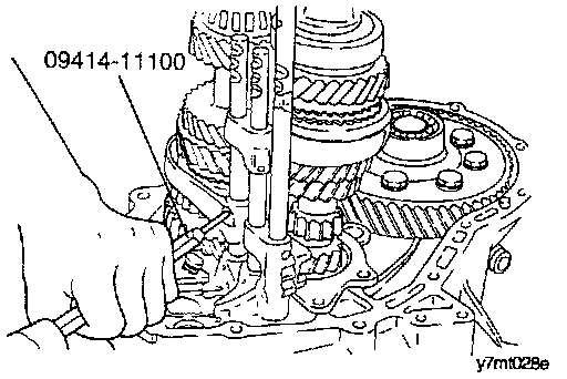
a. Install the spring pins using the special tool (09414 - 11100) or equivalent.
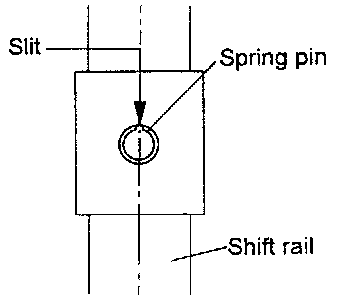
b. When installing, make sure that the slit of the spring pin is aligned with the shift rail center line.
CAUTION: Do not reuse the spring pins.
11. Install the reverse gear lever assembly.
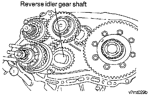
12. Install the reverse gear shaft and reverse gear in the direction illustrated.
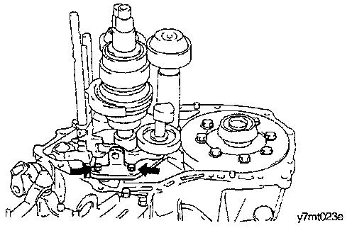
13. Install the reverse shift lever and shoe.
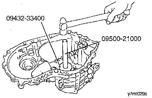
14. Install the input shaft bearing outer race and spacer to the transaxle case using the special tools (09500 - 21000, 09432 - 33400) or equivalents.
15. Install the intermediate shaft bearing outer race and spacer to the transaxle case using the special tools (09500 - 21000, 09432 - 33400) or equivalents.
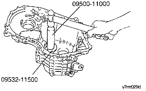
16. Install the output shaft bearing outer race and spacer to the transaxle case using the special tools (09500 - 11000, 09532 - 11500) or equivalents.
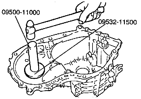
17. Install the differential bearing outer race and spacer to the transaxle case using the special tools (09500 - 11000, 09532 - 11500) or equivalents.
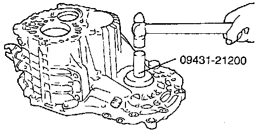
18. Install the drive shaft oil seal to the transaxle case using the special tool (09431 - 21200) or equivalent.
19. Reassembly of spacers (adjustment of end play), as follows:
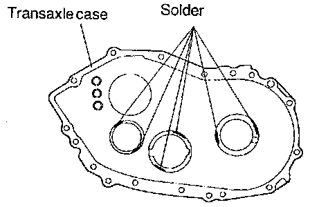
a. Place two pieces of solder measuring about 10 mm (0.4 inch) in length and 3 mm (0.12 inch) in diameter on the bearing outer race as shown in the illustration, and install the outer race.
b. Install the transaxle case and tighten the bolts to the specified torque.
c. Remove the transaxle case.
d. Remove the outer races and remove the solder.
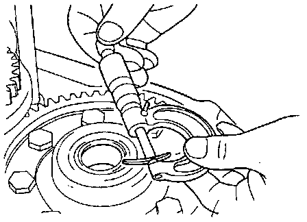
e. Measure the thickness of the crushed solder with a micrometer and select and install a spacer of thickness that gives standard end play.
Standard end play values:
Input shaft:
Front bearing: 0.01T-0.12L mm (0.0004T- 0.0047L inch)
Rear bearing: 0.01T-0.09L mm (0.0004T-0.0036L inch).
Intermediate shaft:
Front bearing: 0.01T-0.11L mm (0.0004T-0.0044L inch).
Rear bearing: 0.05T-0.10T mm (0.002T-0.0039L inch).
Output shaft rear bearing: 0.05T-0.10T mm (0.002T-0.0039T inch).
Differential case: 0.05T-0.10T mm (0.002T-0.0039T inch).
NOTE:
- T indicates tightening of - (minus) direction of end play.
- L indicates loosening of + (plus) direction of end play.
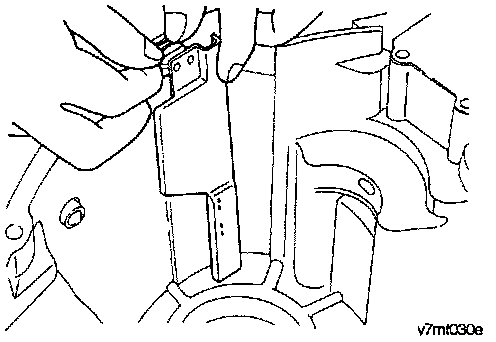
20. Install the oil guide to the transaxle case.
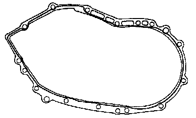
21. Apply specified sealant to the clutch housing side of the transaxle case.
Specified sealant: THREE BOND 1216.
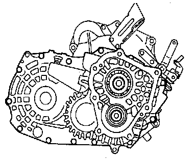
22. Install the transaxle case to the clutch housing assembly and tighten the (13EA) bolts.
23. Install the restriction ball and gasket.
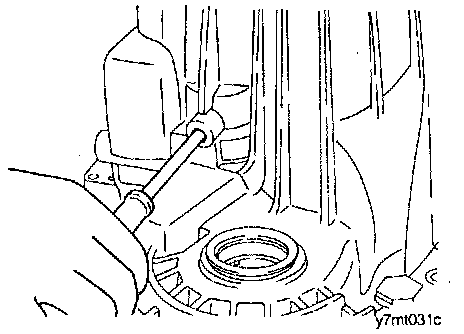
24. Center the shaft with a phillips screwdriver.
25. Tighten the reverse idler gear shaft bolt to the specified torque.
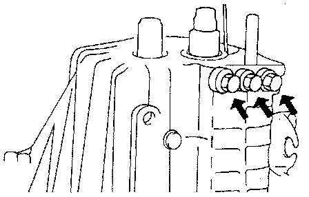
26. Install the poppet balls, poppet springs and poppet plugs.
27. Install the backup lamp assembly.
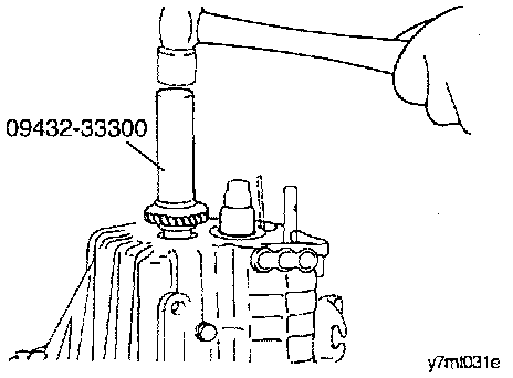
28. Install the intermediate gear using the special tool (09432 - 33300) or equivalent.
29. Install the fifth speed gear and needle roller bearing synchronizer ring, synchronizer hub.
30. Install the fifth speed shift fork and the 5th speed synchronizer sleeve at the same time.
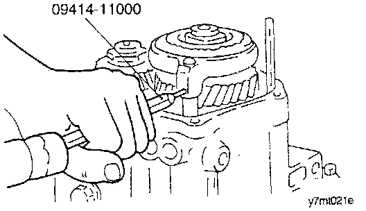
31. Install the spring pin using the special tool (09414 - 11100) or equivalent.
32. When installing, make sure that the slit of the spring pin is aligned with the shift rail center line.
CAUTION: Do not reuse the spring pin.
33. Reassembly of lock nuts, as follows:
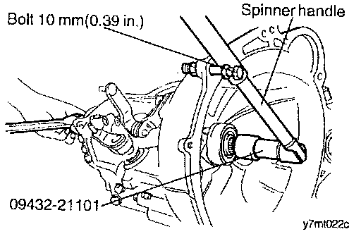
a. Install the special tool (09432 - 21101) or equivalent, onto the input shaft.
b. Screw a bolt 10 mm (0.39 inch) into the hole on the surface of clutch housing and attach a spinner handle to the special tool (09432 - 21101) or equivalent.
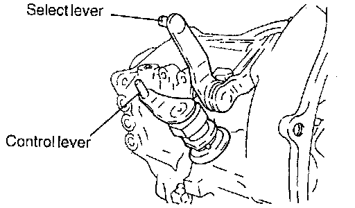
c. Shift the transaxle in reverse using control lever and select lever.
d. Tighten the lock nut to the specified torque.
e. Stake the lock nut.
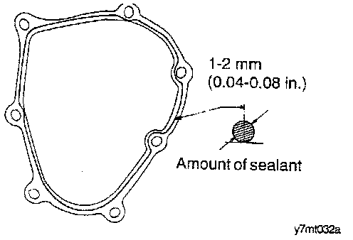
34. Apply the specified sealant to the rear cover and install the rear cover.
Specified sealant: THREE BOND 1216
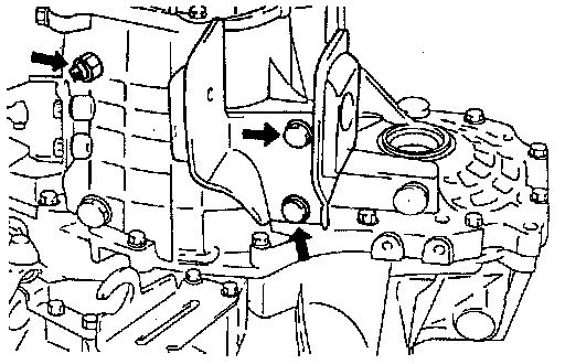
35. Install the backup light switch, gasket and mounting bracket.
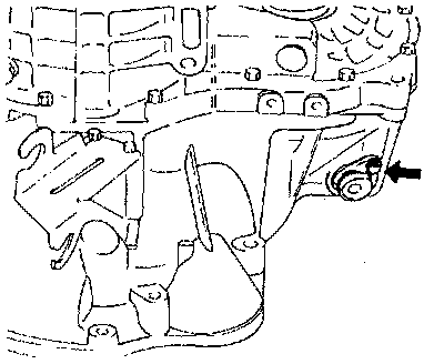
36. Install the speedometer driven gear assembly.