Disassembly
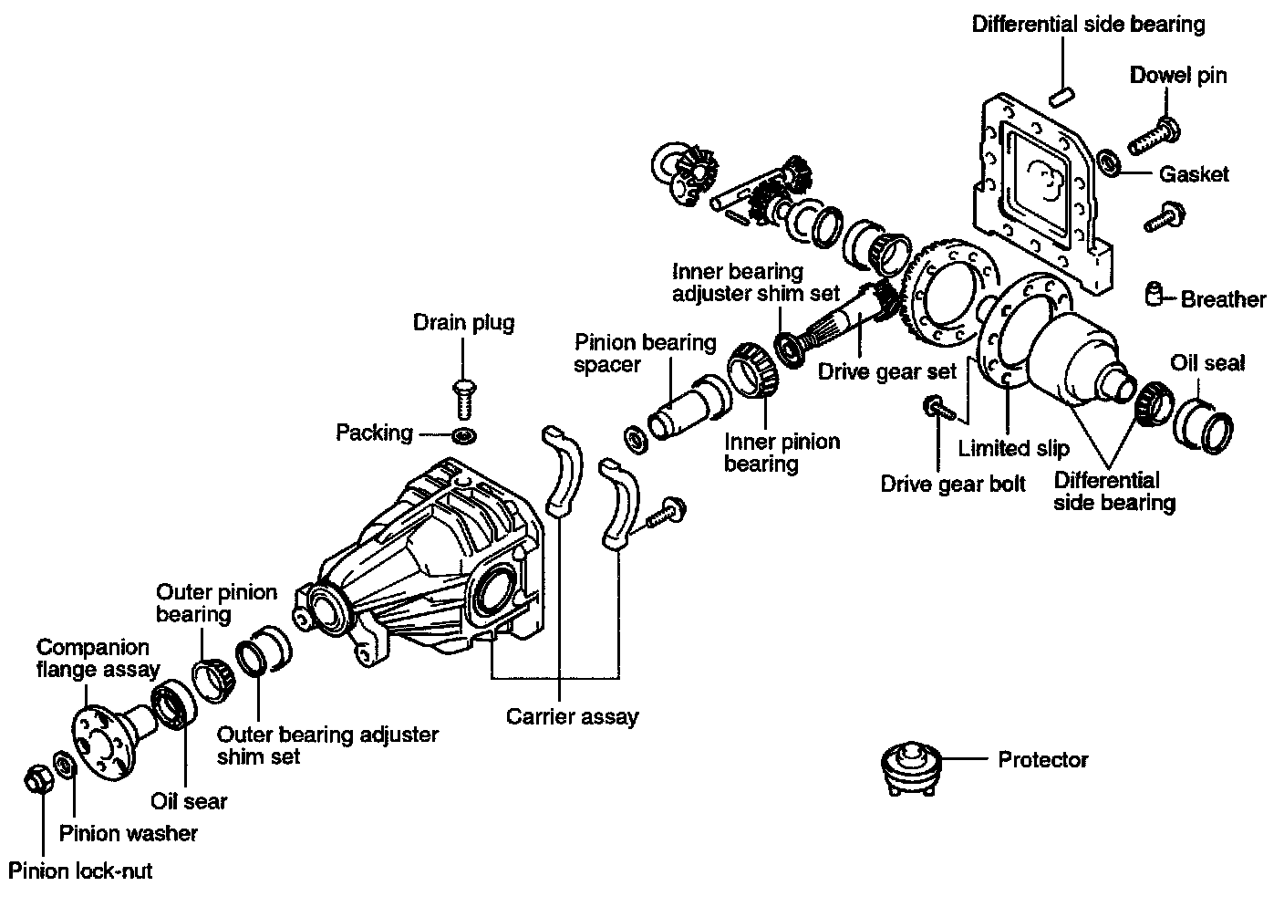
DIFFERENTIAL CARRIER
DISASSEMBLY
1. REMOVAL OF THE DIFFERENTIAL CASE ASSEMBLY
CAUTION: Remove the differential case assembly slowly and carefully. Be careful so that the side bearing outer race is not dropped.
NOTE: Keep the right and left side bearings separate so that they are not mixed during reassembly.
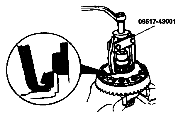
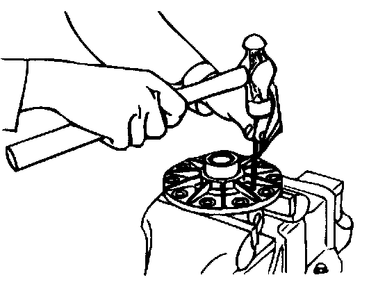
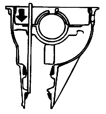
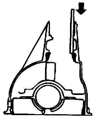
2. REMOVAL OF THE SIDE BEARING INNER RACES
Fit the nut on top of the differential case, and then use the special tool to remove the side bearing inner race.
NOTE: Attach the prongs of the special tool to the inner race of the side bearing through the notched section in the differential case.
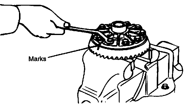
3. REMOVAL OF DRIVE GEAR
a. Make the matchmarks to the differential case and the drive gear.
b. Loosen the drive gear attaching bolts in diagonal sequence to remove the drive gear.
4. REMOVAL OF LOCK PIN (FOR CONVENTIONAL DIFFERENTIAL)
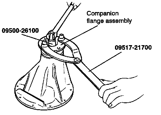
5. REMOVAL OF SELF-LOCKING NUT
6. REMOVAL OF DRIVE PINION
a. Make the matchmarks to the drive pinion and companion flange.
CAUTION: Matchmarks should not be made to the contact surfaces of the companion flange and the propeller shaft.
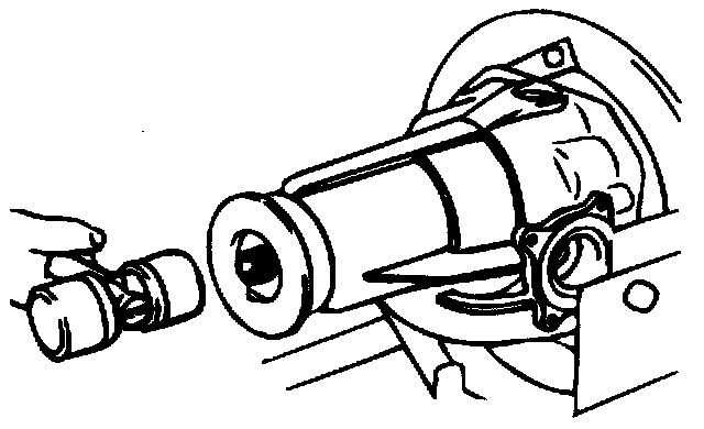
b. Drive out the drive pinion together with the drive pinion spacer and drive pinion front shims.
7. REMOVAL OF DRIVE PINION REAR BEARING INNER RACE
8. REMOVAL OF OIL SEAL / DRIVE PINION FRONT BEARING INNER RACE / DRIVE PINION FRONT BEARING OUTER RACE
9. REMOVAL OF DRIVE PINION REAR BEARING OUTER RACE
INSPECTION
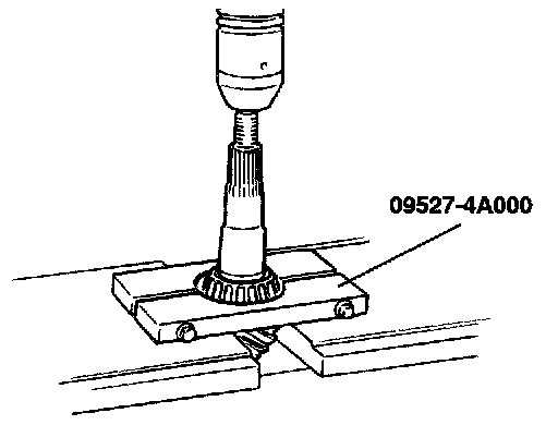
BEFORE DISASSEMBLY:
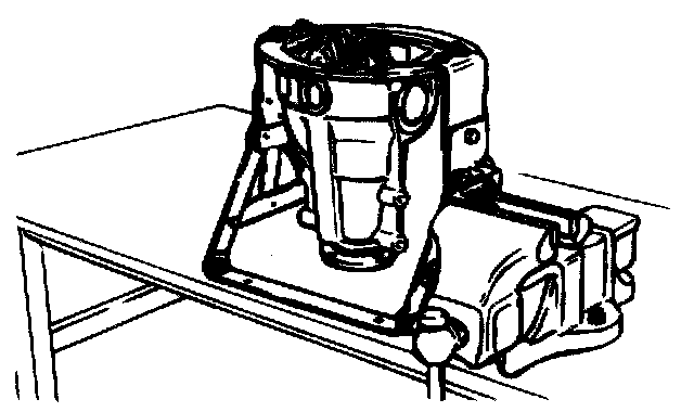
Hold the special tool in a vice, and mount the differential carrier on the special tool.
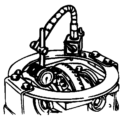
FINAL DRIVE GEAR BACKLASH
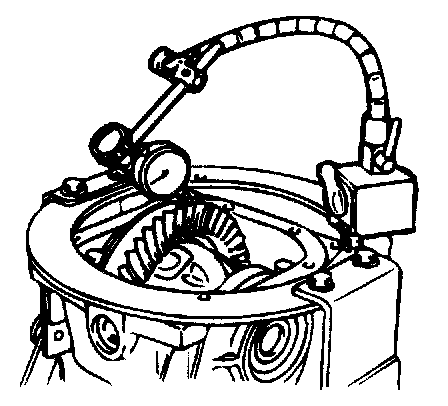
1. Fix the drive gear so it cannot move and measure the final drive gear backlash with a dial indicator.
NOTE: Measure at four points or more on the circumference of the drive gear.
Standard value: 0.08 - 0.13 mm (0.003 - 0.005 inch)
2. If the backlash is beyond the standard value, adjust by using the side bearing spacer.
NOTE: After adjustment, inspect the contact of the final drive gear.
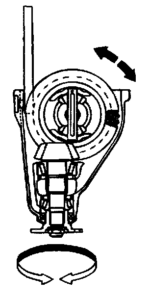
DRIVE GEAR RUNOUT
Check the back-face lash as follows:
1. Place a dial gauge on the back-face of the drive gear and measure the runout.
Limit 0.05 mm (0.0020 inch)
2. If the runout is beyond the limit, check that there are no foreign substances between the drive gear and differential case and, that the bolts fixing the drive gear are not loose.
3. If nothing is wrong in check (2), adjust the drive gear depth and remeasure.
NOTE: If these adjustments are impossible, replace the case or install a new drive gear/drive pinion as a set.
DIFFERENTIAL GEAR BACKLASH
1. Fix the side gear with a wedge so it cannot move and measure the differential gear backlash with a dial indicator on the pinion gear.
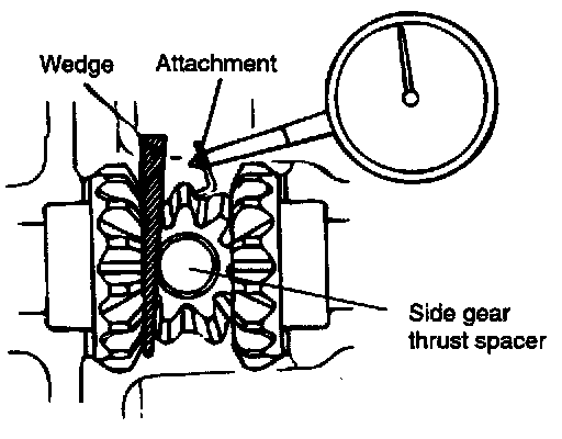
NOTE: Take the measurements at two places (4 places for Limited Slip Differential (LSD) on the pinion gear.
Standard value: 0 - 0.076 mm (0 - 0.003 inch)
Limit: 0.2 mm (0.008 inch)
2. If the backlash exceeds the limit, adjust using side bearing spacers.
NOTE: If adjustment is impossible, replace the side gear and pinion gears as a set.
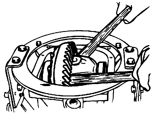
FINAL DRIVE GEAR TOOTH CONTACT
Check the final drive gear tooth contact by following the steps:
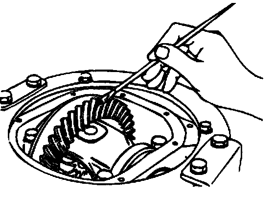
1. Apply a thin, uniform coat of machine blue to both surfaces of the drive gear teeth.
2. Insert a brass rod between the differential carrier and the differential case, and then rotate the companion flange by hand (once in the normal direction, and then once in the reverse direction) while applying a load to the drive gear so that some torque (approximately 25 - 30 kgf-cm) is applied to the drive pinion.
CAUTION: If the drive gear is rotated too much, the tooth contact pattern will become unclear and difficult to check.
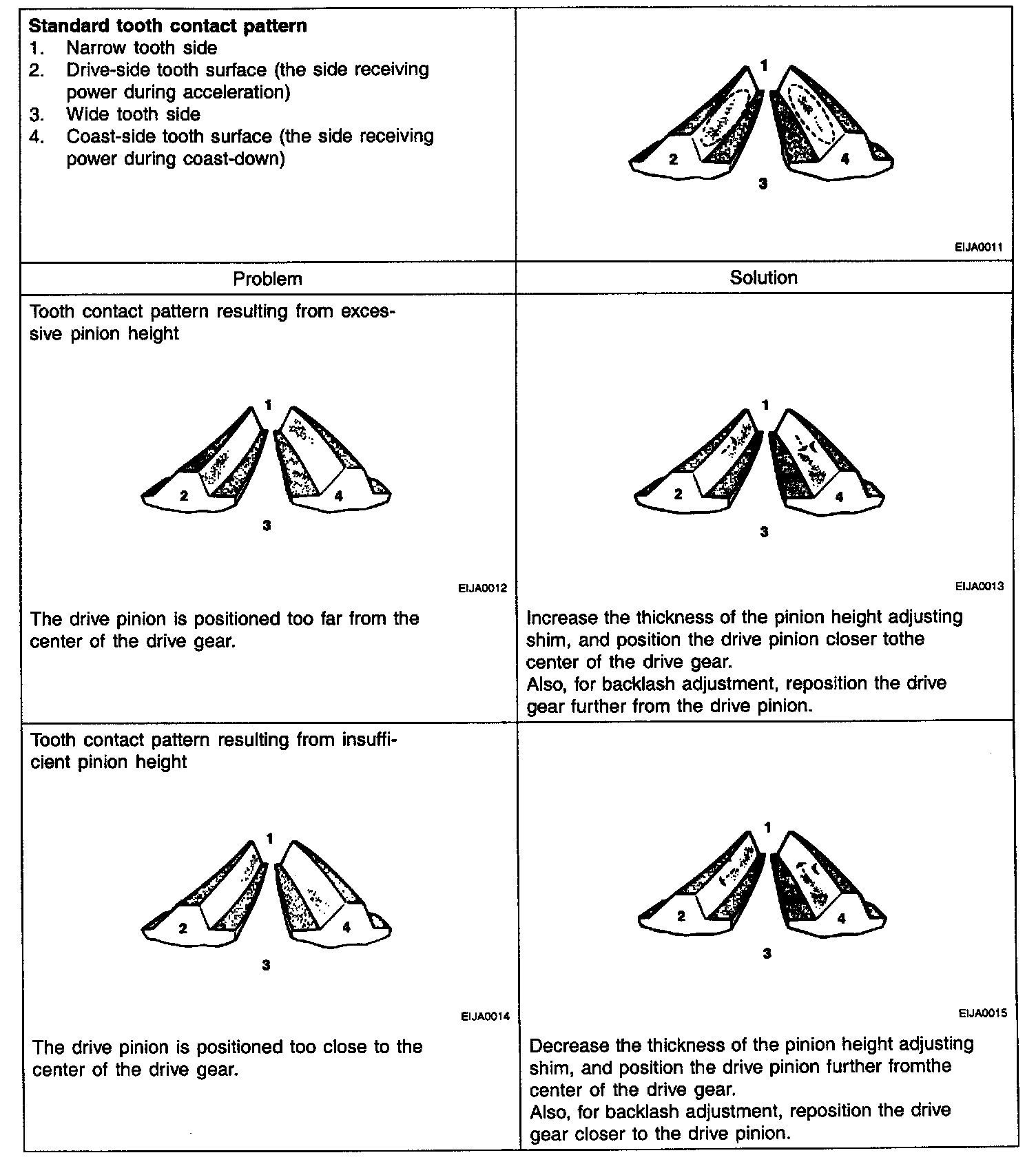
3. Check the tooth contact pattern.
NOTE:
^ Tooth contact pattern is a method for logging the result of the adjustment of drive pinion height and final drive gear backlash. The adjustment of drive pinion height and final drive gear backlash should be repeated until the tooth contact patterns are similar to the standard tooth contact pattern.
^ When you cannot obtain a correct pattern, the drive gear and drive pinion have exceeded their limits. Both gears should be replaced as a set.
AFTER DISASSEMBLY:
1. Check the companion flange for wear or damage.
2. Check the bearings for wear or discoloration.
3. Check the gear carrier for cracks.
4. Check the drive pinion and drive gear for wear or cracks.
5. Check the side gears, pinion gears and pinion shaft for wear or damage.
6. Check the side gear spline for wear or damage.