Cylinder Head Assembly: Testing and Inspection
CYLINDER HEAD ASSEMBLYINSPECTION
CLEANING
1. Clean top surfaces of pistons and cylinder block.
1) Turn the crankshaft, and bring each piston to top dead center (TDC). Using a gasket scraper, remove all the carbon from the piston top surface.
2) Using a gasket scraper, remove all the gasket material from the cylinder block surface.
3) Using compressed air, blow carbon and oil from the bolt holes.
2. Remove gasket material. Using a gasket scraper, remove all the gasket material from the cylinder block contact surface.
CAUTION: Be careful not to scratch the cylinder block contact surface.
3. Clean combustion cambers. Using a wire brush, remove all the carbon from the combustion cambers.
CAUTION: Be careful not to scratch the cylinder block contact surface.
4. Clean cylinder heads. Using a soft brush and solvent. thoroughly clean the cylinder head.
5. Clean valves.
1) Using a gasket scraper, chip off any carbon from the valve head.
2) Using a wire brush thoroughly clean the valve.
CYLINDER HEAD
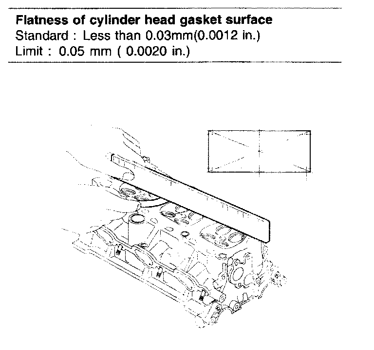
1. Inspect for flatness.
Using a precision straight edge and feeler gauge, measure the surface the contacting the cylinder block for warpage.
Flatness of cylinder head gasket surface
Standard: Less than 0.03 mm (0.0012 inch)
Limit: 0.05 mm (0.0020 inch)
2. Inspect for cracks.
Check the combustion chamber, intake ports, exhaust ports and cylinder block surface for cracks. If cracked, replace the cylinder head.
VALVE AND VALVE SPRING
1. Inspect valve stems and valve guides.
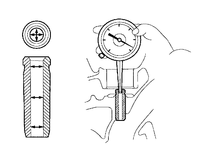
1) Using a caliper gauge, measure the inside diameter or the valve guide. Valve guide inside.
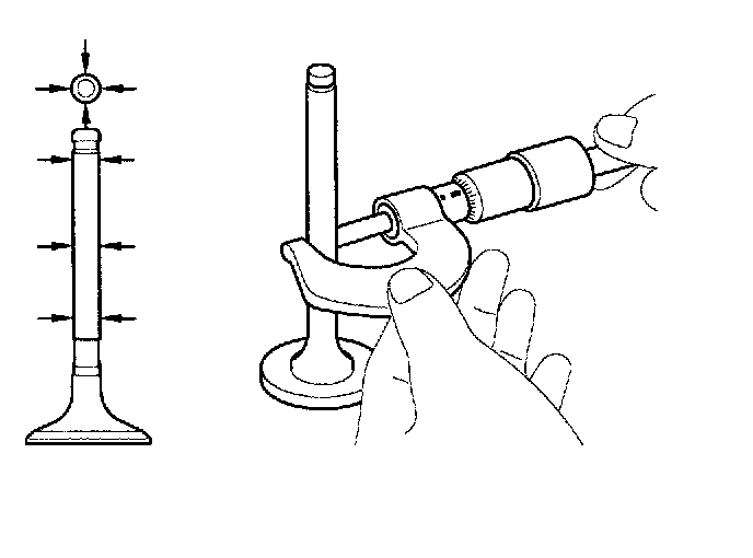
2) Using a micrometer, measure the diameter of the valve stem.
3) Subtract the valve stem diameter measurement from the valve guide inside diameter measurement.
Valve stem-to-guide clearance
[Standard]
Intake: 0.02 - 0.05 mm (0.0008 - 0.0020 inch)
Exhaust: 0.030 -0.065 mm (0.0012 - 0.0026 inch)
[Limit]
Intake: 0.1 mm (0.0040 inch)
Exhaust: 0.13 mm (0.0051 inch)
If the clearance is greater than maximum, replace the valve and valve guide.
2. Inspect valves.
1) Check the valve is ground to the correct valve face angle.
2) Check that the surface of the valve for wear. If the valve face is worn, replace the valve.
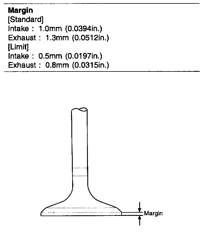
3) Check the valve head margin thickness. If the margin thickness is less than minimum, replace the valve.
Margin
[Standard]
Intake: 1.0 mm (0.0394 inch)
Exhaust: 1.3 mm (0.0512 inch)
[Limit]
Intake: 0.5 mm (0.0197 inch)
Exhaust: 0.8 mm (0.0315 inch)
4) Check the surface of the valve stem tip for wear. If the valve stem tip is worn, replace the valve.
3. Inspect valve seats
Check the valve seat for evidence of overheating and improper contact with the valve face.
Replace the seat if necessary.
Before reconditioning the seat, check the valve guide for wear. If the valve guide is worn, replace it, then recondition the seat. Recondition the valve seat with a valve seat grinder or cutter, The valve seat contact width should be within specifications and centered on the valve face.
4. Inspect valve springs.
1) Using a steel square, measure the out-of-square of the valve spring.
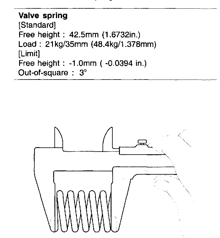
2) Using a vernier calipers, measure the free length of the valve spring.
Valve spring
[Standard]
Free height: 42.5 mm (1.6732 inch)
Load: 21 kg/35 mm (48.4 kg/1.378 mm)
[Limit]
Free height: -1.0 mm (-0.0394 inch)
Out-of-square: 3°
If the free length is not as specified, replace the valve spring.
CAMSHAFT
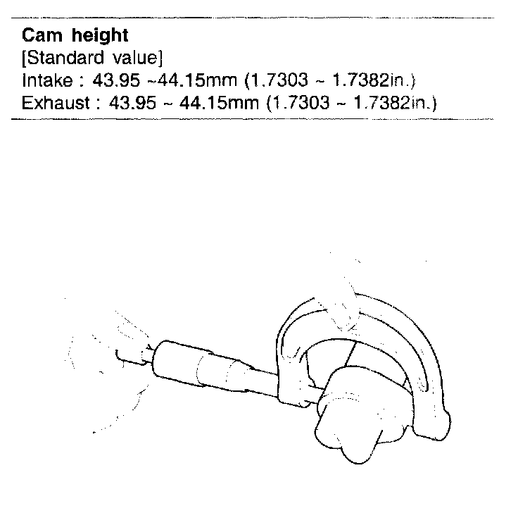
1. Inspect cam lobes.
Using a micrometer, measure the cam lobe height.
Cam height
[Standard value]
Intake: 43.95 -44.15 mm (1.7303 - 1.7382 inch)
Exhaust: 43.95 - 44.15 mm (1.7303 - 1.7382 inch)
If the cam lobe height is less than minimum, replace the camshaft.
2. Inspect cam journals.
Using a micrometer, measure the journal diameter.
Journal diameter
Standard value 25.964 - 25.980 mm (1.0222 - 1.0228 inch)
If the journal diameter is not as specified, check the oil clearance.
3. Inspect camshaft bearings.
Check that bearing for flaking and scoring. If the bearings are damaged, replace the bearing caps and cylinder head as a set.
4. Inspect camshaft journal oil clearance.
1) Clean the bearing caps and camshaft journals.
2) Place the camshafts on the cylinder head.
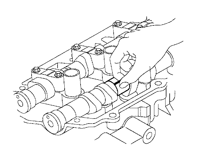
3) Lay a strip of plastigage across each of the camshaft journal.
4) Install the bearing caps.
CAUTION: Do not turn the camshaft.
5) Remove the bearing caps.
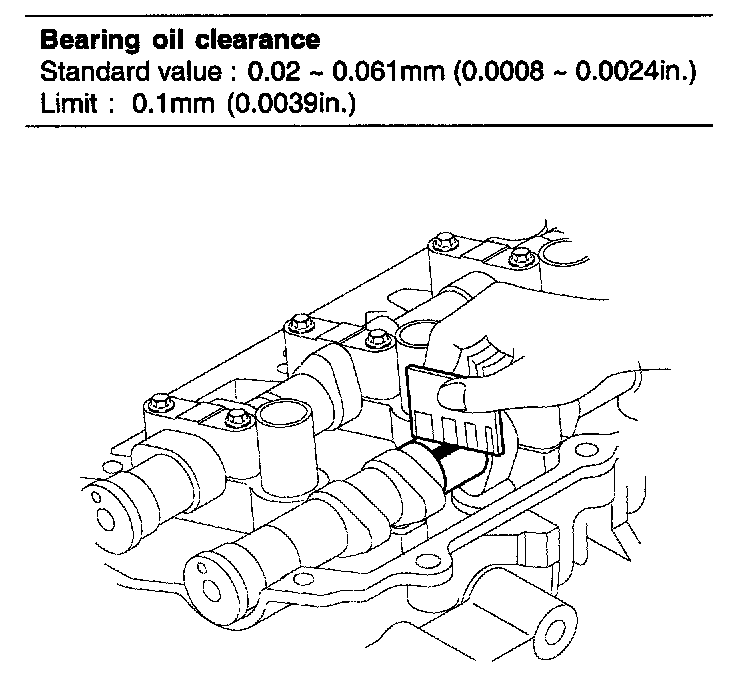
6) Measure the plastigage at its widest point.
Bearing oil clearance
Standard value: 0.02 - 0.061 mm (0.0008 - 0.0024 inch)
Limit: 0.1 mm (0.0039 inch)
If the oil clearance is greater than maximum, replace the camshaft. If necessary, replace the bearing caps and cylinder head as a set.
7) Completely remove the plastigage.
8) Remove the camshafts.
5. Inspect camshaft end play.
1) Install the camshafts.
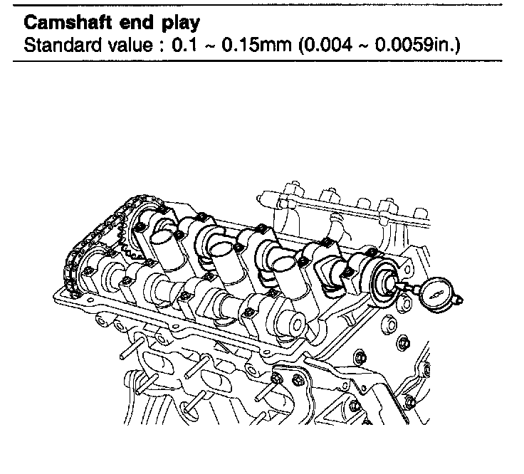
2) Using a dial indicator, measure the end play while moving the camshaft back and forth.
Camshaft end play
Standard value: 0.1 - 0.15 mm (0.004 - 0.0059 inch)
If the end play is greater than maximum, replace the camshaft. If necessary, replace the bearing caps and cylinder head as a set.
3) Remove the camshafts.