Service Procedure
SERVICE PROCEDURE:CAUTION:
Keep all flammable materials away from work area and avoid spilling fuel onto any interior parts.
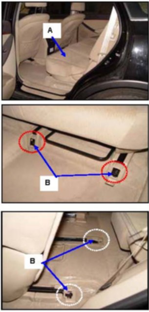
1. Remove the 2nd row left seat (A) by removing the mounting bolts (B). Tightening torque: 29 - 40 lb.ft (4.0 - 5.5 kgf.m).
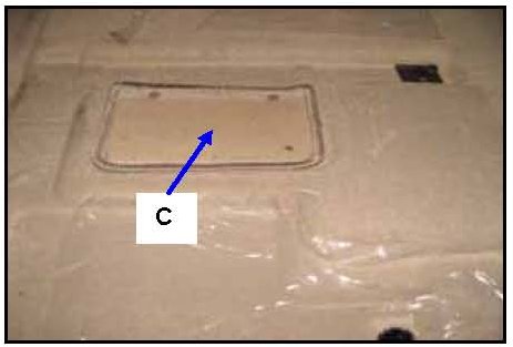
2. Uncover the service access carpet cover (C).
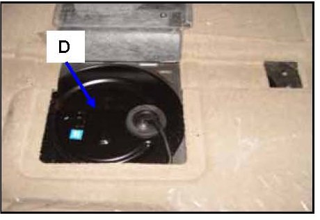
3. Separate the service cover (D) from the floor panel by using a flat blade screwdriver.
Note:
After separating the service cover, be sure to keep and reattach the existing sealant on the back of the service cover. When reinstalling the service cover, press evenly on the outside edge of the service cover by hand.
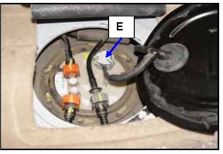
4. Disconnect the fuel tank pressure sensor, fuel sender, and pump wiring connector (E).
5. Start the engine until all fuel in the fuel line is exhausted and then proceed with the remaining steps.
6. After the engine stops, turn the ignition switch off.
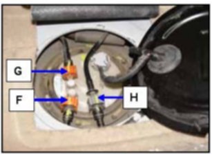
^ F: Fuel feed tube quick connector
^ G: Suction tube quick connector
^ H: Vacuum tube quick connector.
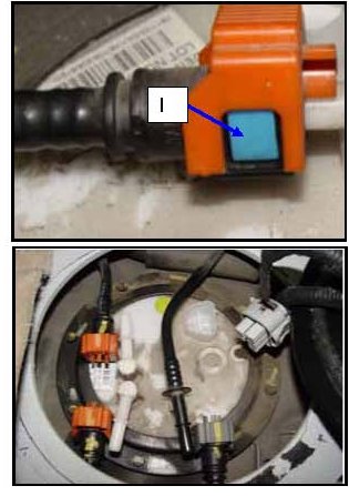
NOTE:
Disconnect the fuel line connectors by pressing on the blue release button (I). To connect the fuel lines, insert the fuel hose back into the connector until a "click" sound is heard.
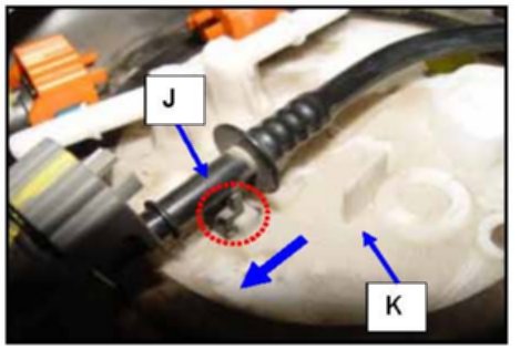
7. Pull the vacuum tube (J) in the direction of the arrow as shown on the photo to remove it from the fuel pump module (K).
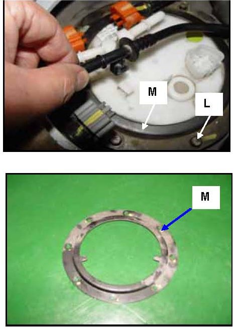
8. Remove the 8 fuel pump module mounting bolts (L) to remove the fuel pump module fixing plate (M).
Tightening torque: 17 - 26 lb. in (0.2 - 0.3 kgf.m)
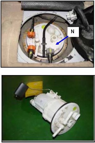
9. Remove the fuel pump / fuel level sensor assembly (N) from the fuel tank.
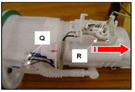
10. Disconnect the fuel level sender and fuel pump motor wiring connector (Q) and then separate the fuel sender assembly (R) from the pump assembly.
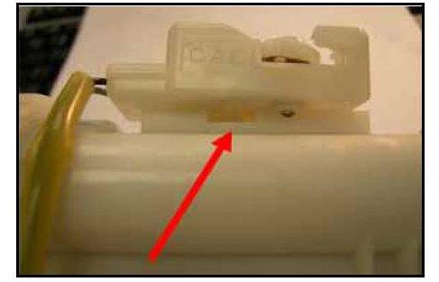
Do this by first depressing the release tab (shown on right) with a pocket screwdriver and sliding the fuel level sender in the direction indicated. (R).
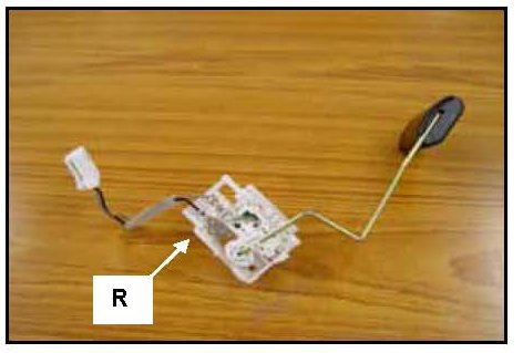
NOTE:
The fuel sender assembly will be reinstalled and must not be damaged.
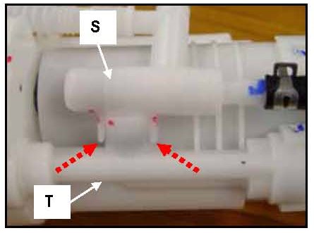
11. Remove the nozzle (S) assembly from the fuel filter (T) using a pocket screwdriver to release the tabs (arrows).
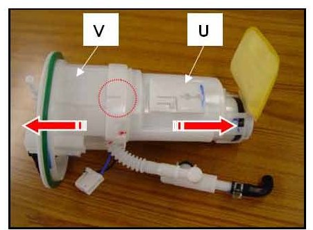
12. Separate the fuel filter (U) from the flange assembly (V) by lifting up on the tabs while pulling in the direction of the arrows.
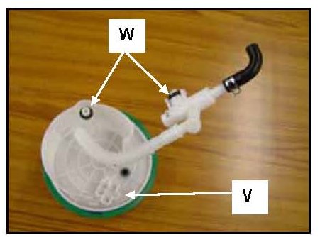
Notes:
(1) The Flange Assembly will be reinstalled when replacing the fuel filter.
(2) Make sure that the 0-rings (W) are installed as shown.
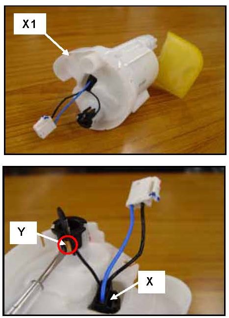
13. Remove the wiring connector (X) and disconnect the terminal (Y) from the removed fuel filter assembly (X1).
NOTE:
Take care to not damage the terminal.
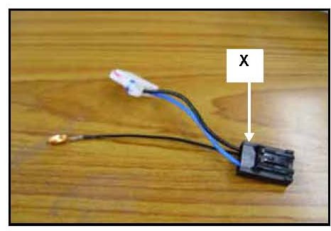
NOTE:
The wiring connector (X) will be reinstalled when replacing the fuel filter.
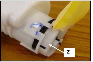
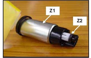
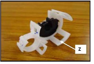
14. Remove the base support (Z) from the fuel filter assembly, then remove the pump assembly (Z1) from the fuel filter assembly.
Notes:
(1) The supporter (Z) and pump assembly (Z1) will be reinstalled when replacing the fuel filter.
(2) Make sure that the 0-ring (Z2) is installed in place.
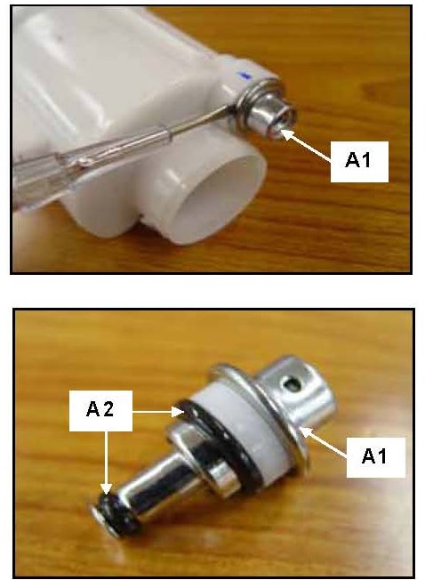
15. Remove the pump regulator assembly (A1) from the fuel filter.
Notes:
(1) The pump regulator assembly (A1) will be reinstalled when replacing the fuel filter.
(2) Make sure that the 0-rings (A2) are installed correctly.
(3) Check 0-rings for physical damage. If 0-ring is cut or cracked, do not reuse damaged 0-rings.
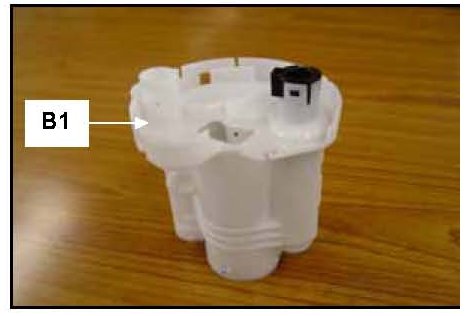
16. Reassemble all reusable parts with the new Fuel Filter (B1) in reverse order of disassembly.
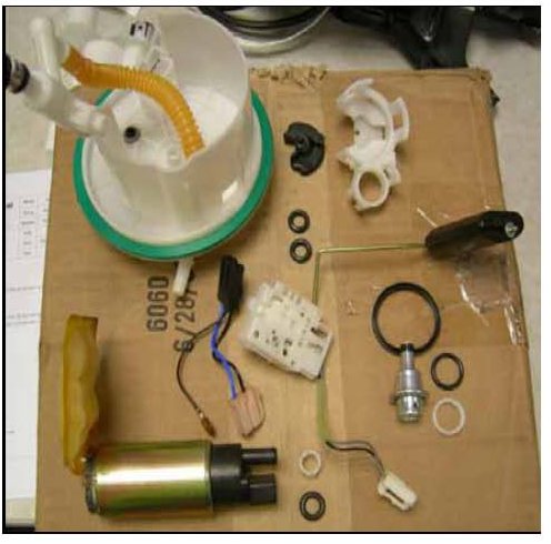
NOTE:
Picture above shows all parts that will be reinstalled.
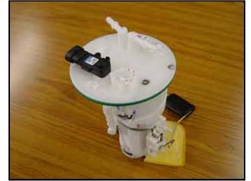
17. Re-install the fuel pump assembly into the fuel tank.
18. Reinstall all removed interior parts in reverse order.