Component Inspection
Component Inspection
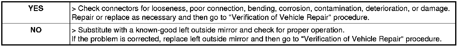
Check left outside mirror switch
1. Connect scantool to Data Link Connector (DLC).
2. Ignition "ON" & engine "OFF"
3. Monitor the "DR. MIRROR UP (DOWN) SW" Parameter on the Scantool. While operating left outside mirror switch.
Specification : Refer the specifications in fig. 1), fig. 2)
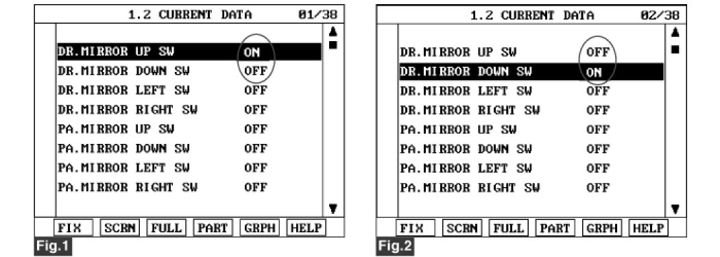
fig. 1) When UP switch is pressed
fig. 2) When DOWN switch is pressed
fig. 1), fig. 2) Current Data of left outside mirror switch.
4. Is the measured current data within specifications ?

Check left outside mirror motor
1. Connect scantool to Data Link Connector (DLC).
2. Ignition "ON" & engine "OFF".
3. Select 'ACTUATION TEST' mode on scantool and press [F1] to start.
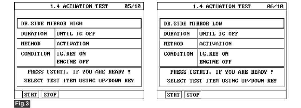
fig. 3) Actuation Test of left outside mirror.
4. Dose left outside mirror motor work properly ?

Check left outside mirror sensor
1. Connect scantool to Data Link Connector (DLC).
2. Ignition "ON" & engine "OFF".
3. Monitor the "MIRROR VERT. POS" Parameter on the Scantool. While operating left outside mirror switch.
Specification : The furthest left -> Approx. 1.0V,
The furthest right -> Approx. 3.5V
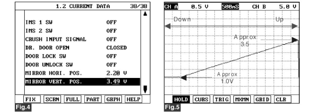
fig. 4) Current Data of left outside mirror vertical position.
fig. 5) Output voltage of outside mirror sensor as a function of vertical position of outside mirror
4. Is the measured voltage within specifications in fig. 5) ?