Automatic Transmission/Transaxle: Description and Operation
Description
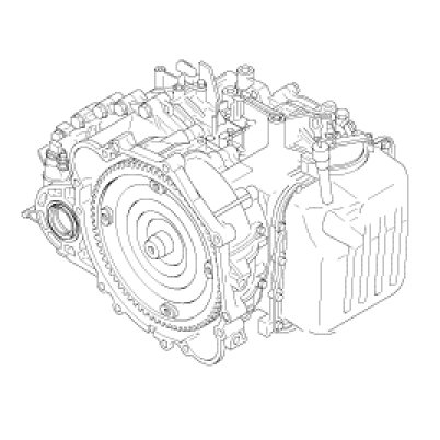
The automatic transmission is a combination of 3-element 2-phase 1-stage torque converter and double shaft electrically-controlled unit which provides 4 speeds forward and 1 reverse. The entire unit is in line with the engine.
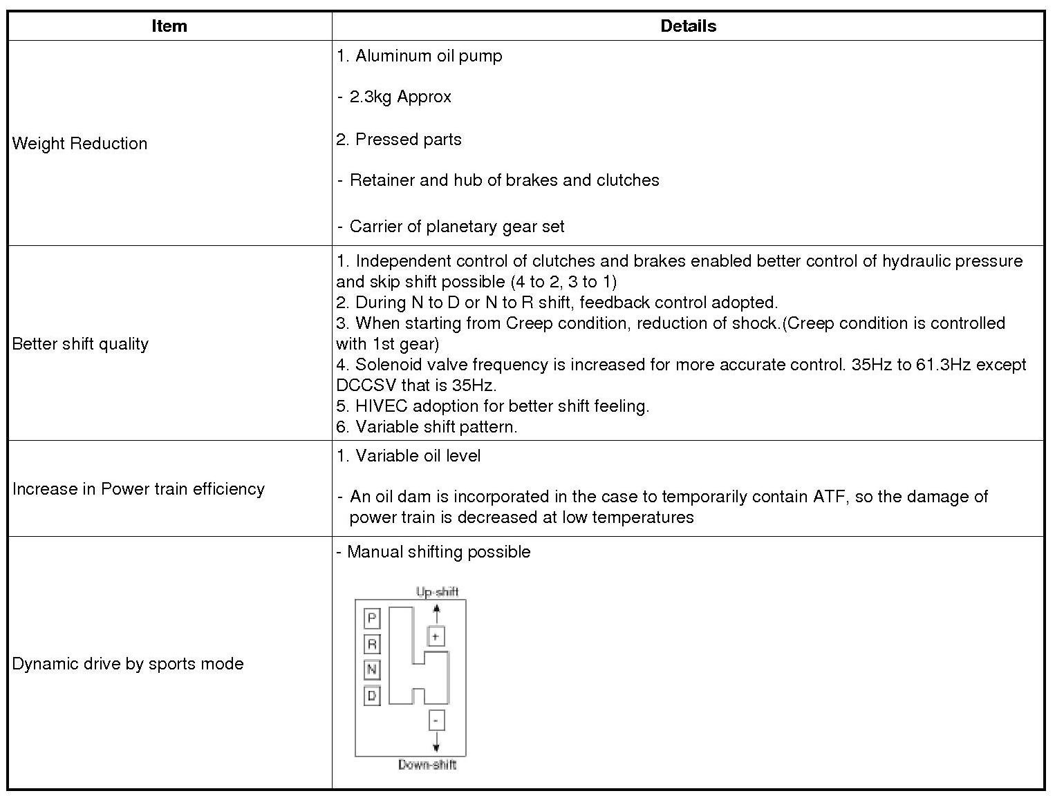
Characteristics
HIVEC: Hyundai Intelligent Vehicle Electronic Control
It differs drastically compared to previous T/M such as alpha, Bcta or KM series automatic transaxles.
All vehicles adopted with an engine volume of 2.0 liters or more has the HIVEC automatic transaxle developed and produced by Hyundai.
Some of the characteristics include:
>Different power transfer
>Different component layout
>New shift logic(HIVEC) to improve shift feeling
>Position of Valve Body
>Variable shift pattern
>Communication protocol and method
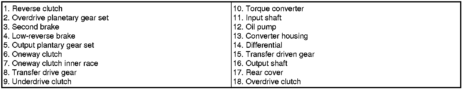
Mechanical System
Operation Components And Function
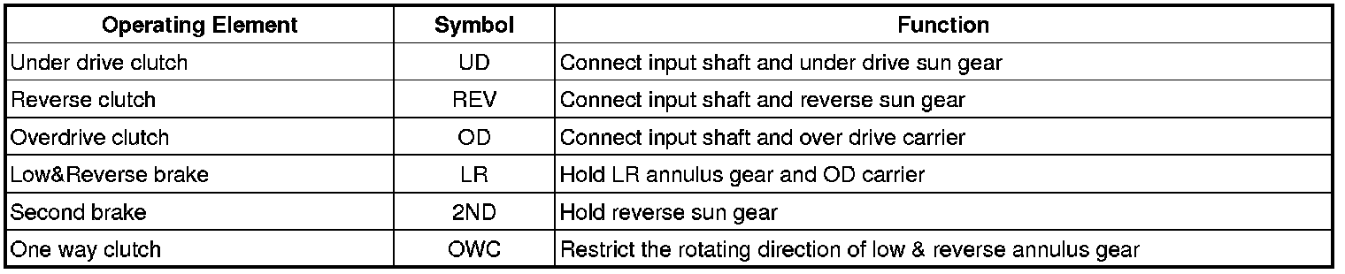
Operating Elements
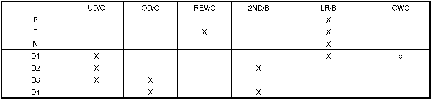
1) O : OWC is operated when shifts from 1st gear to 2nd gear.
2) L&R brake is released in 1st gear when the vehicle speed is more than 5KPH approximately.
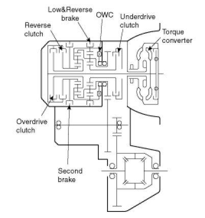
Torque Converter And Shaft
The torque converter consists of a impeller(pump), turbine and stator assembly in a single unit. The pump is connected to the engine crankshaft and turns as the engine turns. This drawing force is transmitted to the turbine through the oil which is recycled by the stator.
The transmission has two parallel shafts ; the input shaft and the output shaft. Both shafts are in line with the engine crankshaft. The input shaft includes the overdrive clutch, reverse clutch, underdrive clutch, one way clutch, 2ND brake, low&reverse brake, overdrive planetary carrier, output planetary carrier and transfer drive gear. The output shaft includes the transfer driven gear.
Clutches
The gear changing mechanism utilizes three multi-disc clutches. The retainers of these clutches are fabricated from high-precision sheet metal for lightness and ease of production. Also, more responsive gearshifts at high engine speeds are achieved by a pressure-balanced piston mechanism that cancels out centrifugal hydraulic pressure. This mechanism replaces the conventional ball check valve.
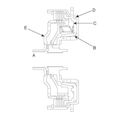
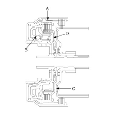
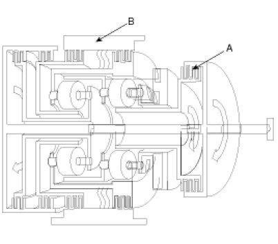
Underdrive Clutch
The underdrive clutch operates in 1st, 2nd, and 3rd gears and transmits driving force from the input shaft to the underdrive sun gear(A).
The components comprising the under clutch are as illustrated below.
Hydraulic pressure acts in the piston pressure chamber(B) (between the piston(c) and retainer) and thus pushes the piston(C). In turn, the piston depresses the clutch discs and thereby transmits driving force from the retainer(D) to the hub(E) side.
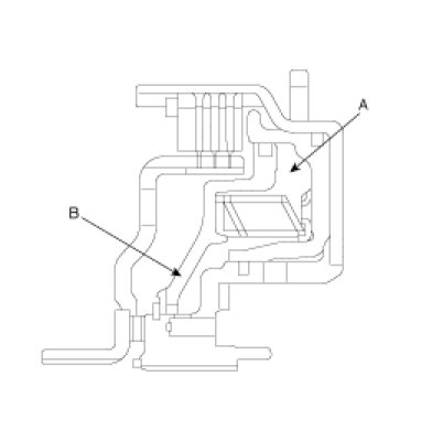
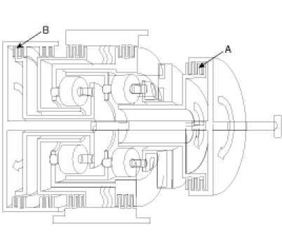
At high speed, fluid remaining in the piston pressure chamber is subjected to centrifugal force and attempts to push the piston.
However, fluid in the balance fluid chamber(A) (the space between the piston and return spring retainer(B)) is also subjected to centrifugal force.
Thus, the hydraulic pressure on one side of the piston cancels out the hydraulic pressure on the other side, and the piston does not move.
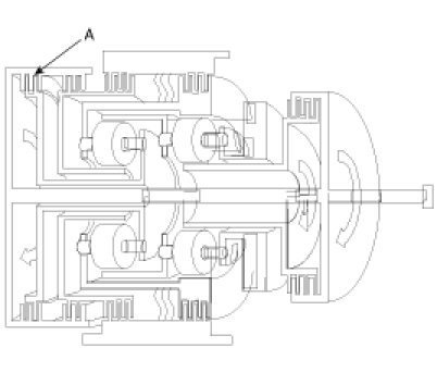
Reverse Clutch And Overdrive Clutch
The reverse clutch(C) operates when the reverse gear is selected and transmits driving force from the input shaft to the reverse sun gear.
The overdrive clutch(D) operates in 3rd and 4th gears and transmits driving force from the input shaft to the overdrive planetary carrier and low-reverse annulus gear.
Brakes
The gear changing mechanism utilizes two multi-disc brakes.
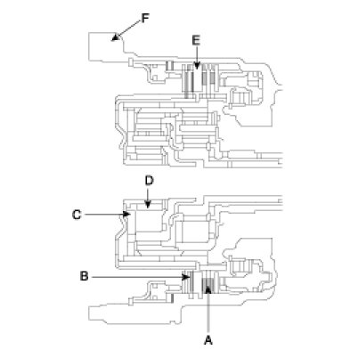
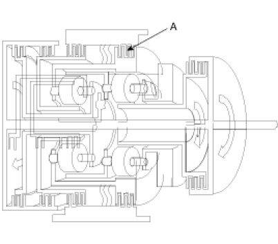
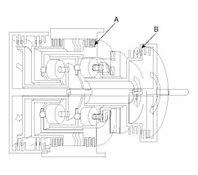
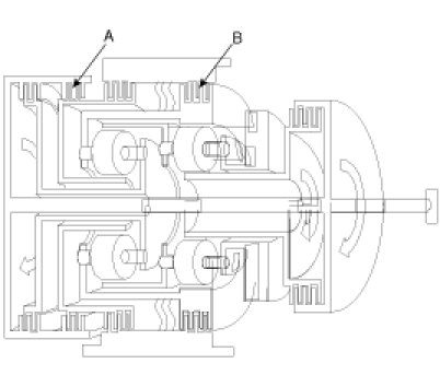
Low-reverse Brake And Second Brake
The low-reverse brake(A) operates in 1st and reverse gears, when the vehicle is parked, and during manual operation. It locks the low-reverse annulus gear and overdrive planetary carrier to the case.
The second(C) brake(B) operates in 2nd and 4th gears and locks the reverse sun gear(D) to the case.
The components comprising the low-reverse brake and second brake are as illustrated below.
As shown, the discs and plates of the two brakes are arranged on either side of the rear cushion plate(E), which is itself secured to the case(F) by a snap ring.
OWC
To improve the shift feeling from 1st. to 2nd gear, OWC was adopted on the Low&reverse brake annulus gear. Instead of hydraulic fixing by Low&reverse brake at the 1st gear, this mechanical fixing device was used. This structure is not new concept, because this OWC already has been installed on the:
Accumulators

Objective
* Energy (hydraulic pressure) storage
* Impact and pulsation damping when solenoid valves operating
* Operation as spring element
* Smooth shifting by preventing sudden operation of clutches and brakes
Transfer Drive Gear
With the transfer drive gear, increased tooth height and a higher contact ratio have reduced gear noise.
Also, the bearing that supports the drive gear is a preloaded type that eliminates rattle, and the rigidity of the gear mounting has been increased by bolting the bearing directly onto the case.
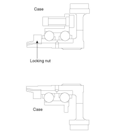
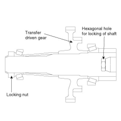
Output Shaft/transfer Driven Gear
As shown in the illustration below, the transfer driven gear is press-fitted onto the output shaft, and the output shaft is secured by a locking nut and supported by bearings.
The locking nut has a left-handed thread, and a hexagonal hole in the other end of the shaft enables the shaft to be held in position for locking nut removal.
Manual Control System
Manual Control Lever
The manual control lever is fitted to the top of the valve body and is linked to the parking roller rod and manual control valve pin.
A detent mechanism is provided to improve the gear shift feeling during manual selection.
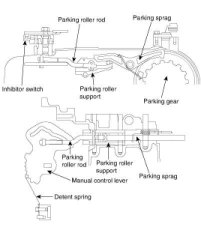
Parking Mechanism
When the manual control lever is moved to the parking position, the parking roller rod moves along the parking roller support and pushes up the parking sprag.
As a result, the parking sprag meshes with the transfer driven gear (parking gear), thereby locking the output shaft. To minimize the operating force required, a roller is fitted to the end of the rod.
Power Train
P Position
Hydraulic pressure is applied to the LR brake and the RED brake, so power is not transmitted from the input shaft to the UD clutch or OD clutch, and the output shaft is locked by the park brake pawl interlocking the park gear.
N Position
Hydraulic pressure is applied to the LR brake(A) and the RED brake, so power is not transmitted from the input shaft to the UD clutch or OD clutch.
1st Gear Power Flow
Hydraulic pressure is applied to the UD clutch(B) the LR brake(A) and the one way clutch(OWC), then the UD clutch transmits driving force from the input shaft to the UD sun gear, and the LR brake locks the LR annulus gear to the case.The UD sun gear of the planetary gear drives the output pinion gear, and the LR brake locks the annulus gear, and the output pinion drives the output carriers, and the output carrier drives the transfer drive gear, and the transfer drive gear drives the transfer driven gear of the output shaft, and power is transmitted to the differential gear through the differential drive gear.
2nd Gear Power Flow
Hydraulic pressure is applied to the UD clutch(A) the 2nd brake(B) and the one way clutch(OWC), then the UD clutch transmits driving force from the input shaft to the UD sun gear, and the 2nd brake locks the reverse sun gear to the case.The UD sun gear of the planetary gear drives the output pinion gear and the LR annulus gear, and the LR annulus gear drives the OD planetary carriers, and OD planetary carriers drives OD pinion gear, and the OD pinion gear drives the output carriers, and the output carrier drives the transfer drive gear, and the transfer drive gear drives the transfer driven gear of the output shaft, and power is transmitted to the differential gear through the differential drive gear.
3rd Gear Power Flow
Hydraulic pressure is applied to the UD clutch(A) and the OD clutch(B), then the UD clutch transmits driving force from the input shaft to the UD sun gear, and the OD clutch transmits driving force from the input shaft to the overdrive planetary carrier and low-reverse annulus gear.The UD sun gear of the planetary gear drives the output pinion gear and the LR annulus gear, and the LR annulus gear drives the OD pinion gear through the OD planetary carrier, and the OD pinion gear drives the reverse sun gear and the output carrier.The OD clutch drives the OD carrier, and the OD carrier drives the OD pinion gear, and the OD pinion gear drives the reverse sun gear and the output carrier, and the output carrier drives the transfer drive gear, and the transfer drive gear drives the transfer driven gear of the output shaft, and power is transmitted to the differential gear through the differential drive gear.
4th Gear Power Flow
Hydraulic pressure is applied to the OD clutch(A) and the 2nd brake(B), then the OD clutch transmits driving force from the input shaft to the OD planetary carrier and LR annulus gear, and the 2nd brake locks the reverse sun gear to the case.The OD clutch drives the OD carrier, and the OD carrier drives the OD pinion gear and the LR annulus gear, and the OD pinion gear drives the output carrier, and the output carrier drives the transfer drive gear, and the transfer drive gear drives the transfer driven gear of the output shaft, and power is transmitted to the differential gear through the differential drive gear.
Rev Gear Power Flow
Hydraulic pressure is applied to the reverse clutch(A) and the LR brake(B), then the reverse clutch transmits driving force from the input shaft to the reverse sun gear, and the LR brake locks the LR annulus gear and OD planetary carrier to the case.The reverse clutch drives the reverse sun gear, and the reverse sun gear drives the output carrier through the OD pinion gear, and the output carrier drives the transfer drive gear, and the transfer drive gear drives the transfer driven gear of the output shaft, and power is transmitted to the differential gear through the differential drive gear.
Hydraulic Control System
Description
- Better and smoother shift quality.
- In order to prevent ATF leakage from the valve body or each elements, the exhaust ports have been grouped into only one with an addition of a check ball.
- If a failure occurs in its electric control, the switch valve and fail safe valve is able to move to enable 3rd speed drive or reverse.
- The hydraulic system consists of oil pump, regulator valve, solenoid valves, pressure control valve and valve body.
Operation Components And Functions
Oil Pump
The oil pump is made of aluminum to reduce its weight. The oil pump is not a serviceable part; it must be replaced as a pump assembly.
Do not disassemble the pump as improper alignment during assembly will cause pump failure and could cause damage to the transaxle.
When removing the oil pump from the T/M case, the S.S.T. (09452-33100) must be used.
Operation Of Each Valve
Torque converter pressure control valve : The function of this valve is to maintain a constant pressure within the torque converter.
Damper clutch control valve : Its function is to control the hydraulic pressure that acts on the Damper Clutch. Manual valve :The position of the manual valve is determined by the selector lever and applies or cuts line pressure to different valves.
Pressure control valve & Solenoid valve : The pressure control valve prevents a rapid decrease in hydraulic pressure when the clutch becomes disengaged. It also reduces the sharp increase in input shaft speed during clutch to clutch control.
Switch valve : When the OD clutch is applied, the hydraulic pressure is applied to the regulator valve via the switch valve. Hence, the line pressure is reduced at 3rd and 4th gear.
Fail Safe Valve-A : During fail safe mode, this valve releases the pressure in the LR Brake.
Fail Safe Valve-B : During fail safe mode, this valve cuts the pressure from the 2nd pressure control valve to 2nd brake.
Electronic Control System
Description
The electronic control system used in the new generation auto transaxle is far superior to the previous systems. This system is able to adopt a variable shift pattern for smooth and problem free shifting.
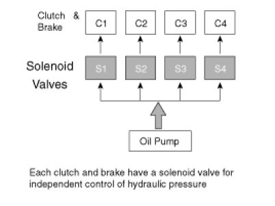
A solenoid valve is applied to each of the clutches and brakes and is independently controlled. Feedback control and correction control is performed in all gears as well as utilization of mutual control system to increase shift feeling.
The torque converter damper clutch uses a partial lock up and full lock-up system. An additional control method called the HIVEC system (neural network) is adopted to increase shift feeling.
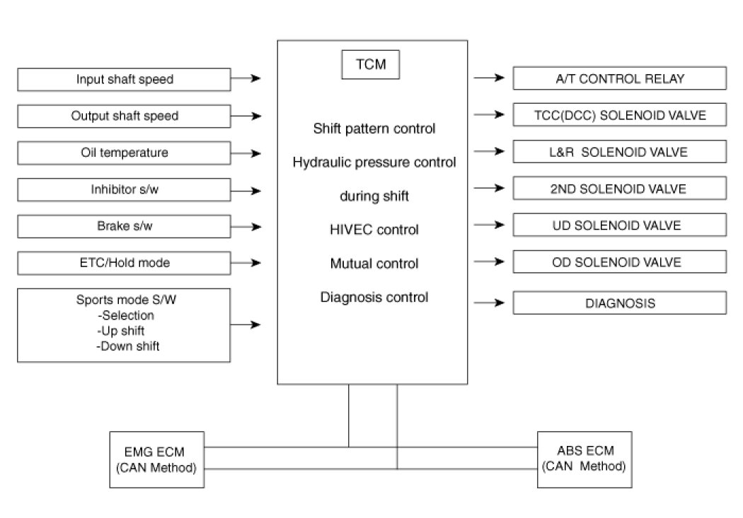
Block Diagram (CAN)
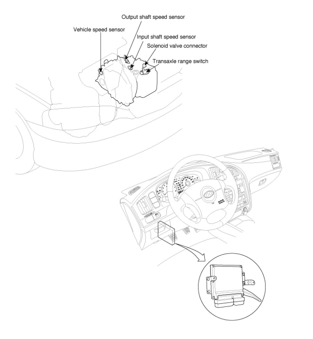
Electric Control Location
The TCM is located below the dashboard. However, in the Beta-engine vehicles, there is not TCM but PCM.
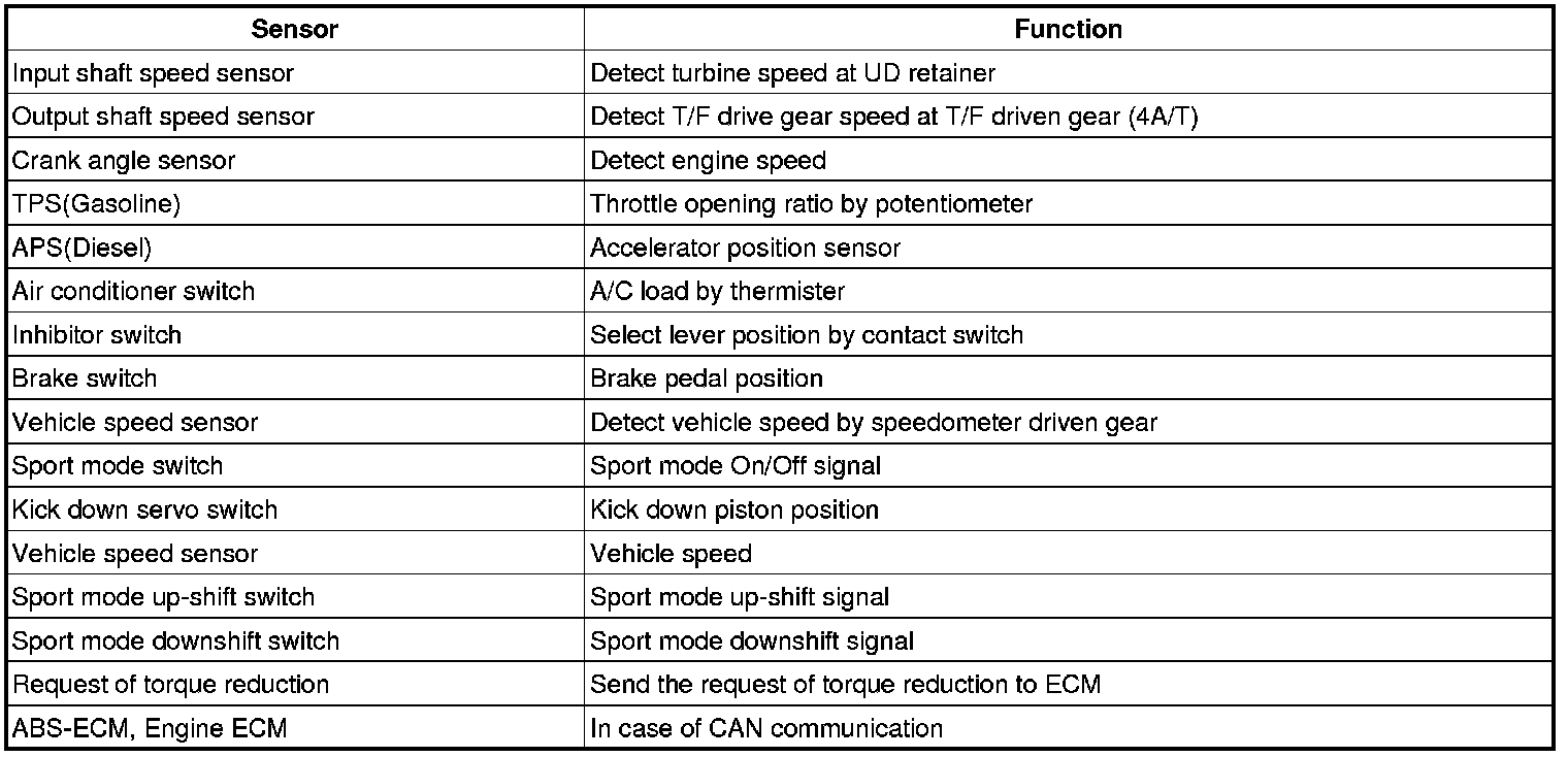
Operating Components And Functions
HIVEC
In addition to the variable shift pattern control, the HIVEC system with neural network is also adopted for the first time in HMC. HIVEC uses information from various inputs and feedback adaptation and selects the best appropriate gear position and shift timing under all possible driving conditions.
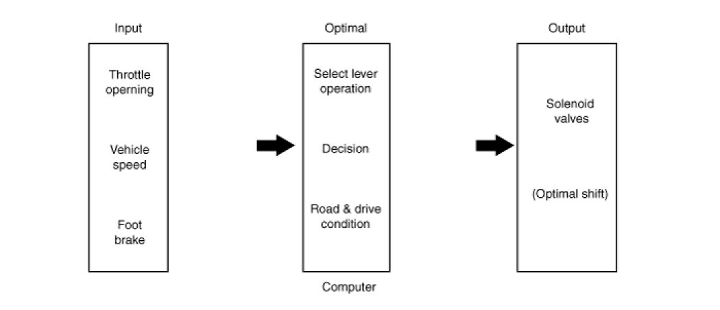
Control For All Driving Condition
This function makes TCM decide optimal gear range under all driving condition. The optimal operation of the manual shift lever by several drivers' and various driving condition is pre-set in the TCM. On the basis of mapping data, TCM decides the driving condition from throttle opening, vehicle speed and brake signal. And then TCM controls the gear position optimally. Optimal gear position is achieved under various driving condition by HIVEC logic.
Optimal Control For All Driving Condition
HIVEC Inhibit Conditions
- ATF temperature below 40°C.
- When standard pattern is not used.
- Inhibitor switch: P, R, N, L
- Extremely low temperature mode
- Lower emission shift pattern
- ATF control variable shift pattern
- During fail safe mode (3rd gear hold)
- In case of prohibition of Intelligent shift
- TPS faulty (Short: P1702, Open: 1701)
- ATF Temperature sensor faulty (P1712)
- Stop lamp s/w faulty (P0703)
- TCM faulty (Check engine lamp ON)
- After IG ON until first time stop lamp S/W comes ON->OFF.
Sports Mode
Sports Mode Switch
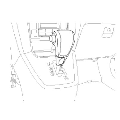
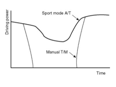
Sports mode allows the manual up-shift and downshift with the accelerator pedal is depressed. The prompt response and shift would be obtained due to the continuous shifting without cutting of driving power. The shifting time is also decreased about 0.1sec during up-shift, 0.2sec during downshift. As the selector lever is pushed upward or downward one time, the gear is up shifted or downshifted by one gear.
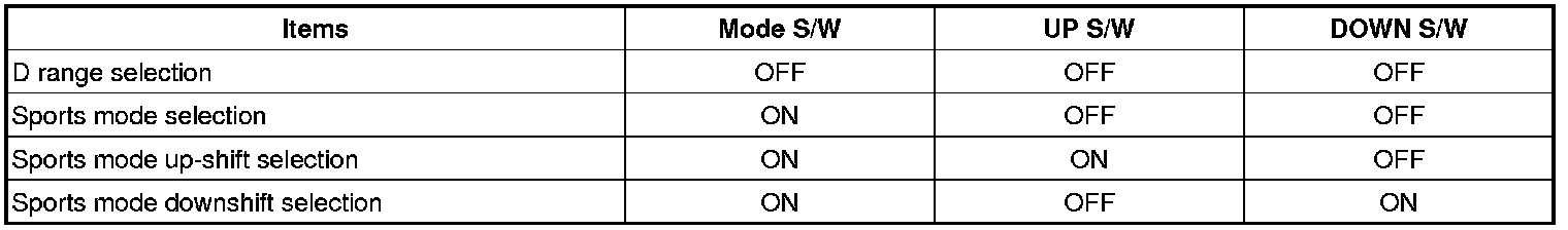
Signals of sports mode switch
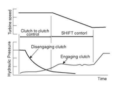
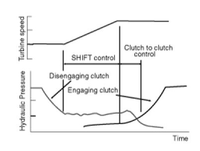
Clutch To Clutch Shift Control
As can be seen in the solenoid valve layout below, there are major differences between the previous A/T and New A/T.
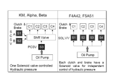
In previous A/T, there were only two solenoid valves to enable shift and one solenoid valve to control hydraulic pressure which resulted in inaccurate shift and rough ride.
In the new A/T which is adopted for the EF and XG-Car, there are solenoid valves for each clutch&brake which enable control of both the disengaging and engaging clutch simultaneously for independent control. This system provides a much smoother shift and comfortable ride as well as preventing Engine run-up or clutch interlock. In addition to advanced shift feeling, the 1st gear is selected at the creep state for eliminating the shift shock during 2nd gear -> 1st gear.
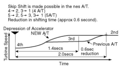
Skip Shift Control
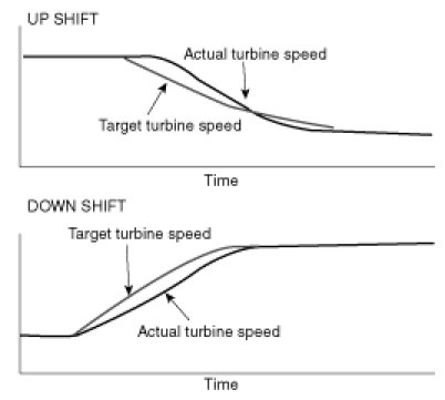
Feedback Shift Control
The turbine speed is monitored and controlled during shifting to satisfy target turbine speed which is accomplished by feedback control of solenoid valve duty value. Therefore the compensation of torque for the outworn engine or A/T is possible. This has resulted in the ability to control the change in torque during shifting and produce smooth shift and better shift feeling. Feedback shift control is also applicable in N->D and N->R.
Damper Clutch Control
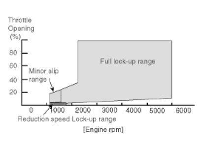
The Lock-up clutch is designed in a torque converter for the fuel economy. The lock-up clutch works in low speed range as minor slip.And it operates in high speed range as Full lock-up. Low fuel consumption and silence can be obtained with combination of Partial lock-up and Full lock-up control.The damper clutch is operated in 3rd and 4th gear in 4-speed ATA, 4th and 5th gear in 5ATA. In addition, Lock-up control is adapted in order to improve the fuel economy, when reducing vehicle speed too.
Damper Clutch Operating Range
As all the conditions below are satisfied, it locks up. The cross point of throttle opening and turbine rpm is within shadowed area.
- D range (more than 2nd speed), but damper clutch operating in 2nd speed, the ATF temperature must be higher than 125 °C.
- The TCM does not control under N -> D or N -> R.
- Oil temperature is above 50°C under full lock-up.
- Oil temperature is above 70°C under minor slip.
- The system is not under Fail - Safe (3rd gear hold) condition.
Uphill (above 5%) longer than 1.5sec. : Reducing speed Lock-up During this control, the vehicle is running uphill (less than 2.5%) for 1sec., the partial lock-up control is functioned again.
Serial Communication Interface (SCI)
This uses a integrated computer which contains both the ECM and the TCM within the same unit. We will refer to this unit as integrated ECM.
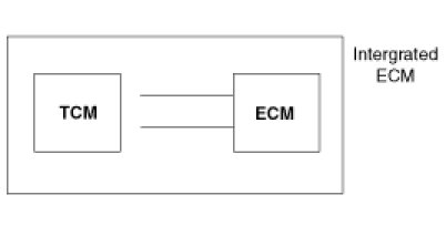
Communication Speed: 15.625Kbit/sec
Frequency: 20ms
If a fault occurs in either ECM or TCM, the entire integrated ECM must be replaced.
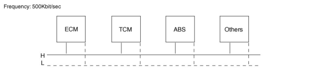
Controller Area Network (CAN)
Previously, for different computers in the vehicle to share the same information, each signal required a different pin and wiring. However, with the introduction of a CAN system, only two lines are required to achieve the same function. The information is in digital format. This method does not use a integrated ECM.
Input signals to TCM through 'CAN communication'
- Engine rpm, TPS signal
- A/CON signal, Engine coolant temperature
- Quantity of intake airflow, Vehicle speed
- Shift holding signal (FTCS ON)
Output signals from TCM through 'CAN communication'
- Request signal for torque reduction
- ATF temperature, TCM type, TCM error or not
- Damper clutch ON, OFF / Gear position