Repair Procedures
Removal
1. Loosen the wheel nuts slightly. Raise the front of the vehicle, and make sure it is securely supported.
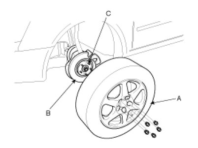
2. Remove the front wheel and tire(A) from front hub(B).
CAUTION:
Be careful not to damage the hub bolts(C) when removing the front wheel and tire(A).
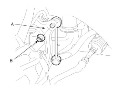
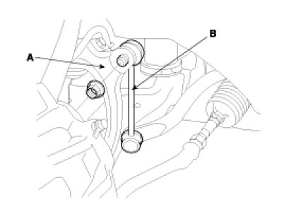
3. Remove the stabilizer link(B) from the fork(A).
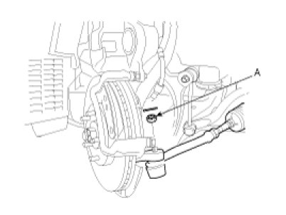
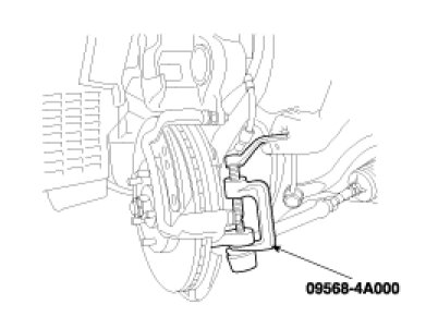
4. After removing both sides of the tie rod end self-locking nuts(A), remove the ball joint by using the special tool(09568-4A000).
5. Remove both sides of the lower arm mounting bolts(A).
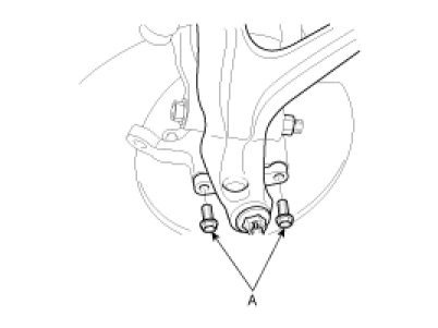
CAUTION:
Be careful not to damage the bolts(A).
6. Remove both sides of the connecting bolts(A) between the lower arm and the fork.
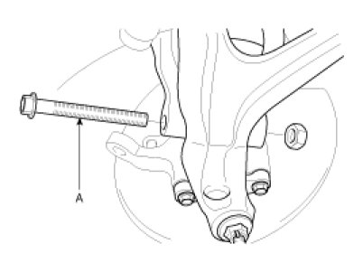
CAUTION:
Be careful not to damage to the aluminium lower arm.
7. Remove the connecting bolt(A) between the steering universal joint assembly and the pinion assembly.
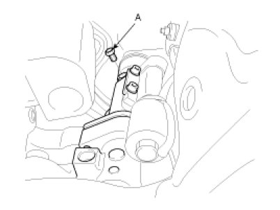
CAUTION:
Keep the neutral-range to prevent the damage of the clock spring inner cable when you handle the steering wheel.
8. Remove the engine mounting bolts(A,B)
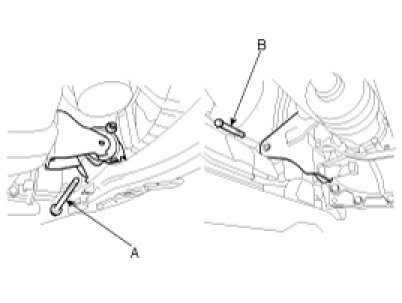
9. Remove the eight bolts and nuts of the sub frame by supporting it with a jack.
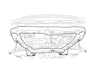
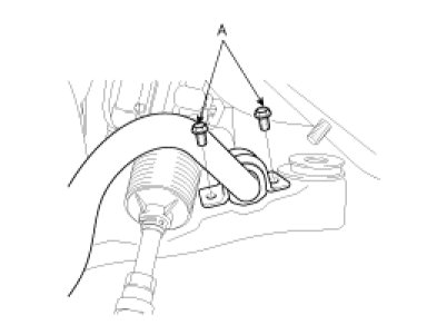
10. After lowering the jack which supports the sub frame in a proper level, remove both sides of the stabilizer bar assembly mounting bolts(A).
11. Remove the stabilizer bar assembly through the gap between the body and the rear side of the sub frame.
CAUTION:
Be careful not to damage to the power steering related tubes.
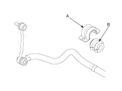
12. Remove the brackets(A) and the bushings(B).
Inspection
1. Check the bushing for wear and deterioration.
2. Check the stabilizer bar for bending or breakage.
3. Check the ball joint for rotating torque.
(1) If there is a crack in the dust cover, replace it and add grease.
(2) Move the stabilizer link ball joint stud several times in a circular motion.
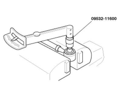
(3) Mount the self-locking nut on the ball joint, and then measure the ball joint rotating torque.
Standard value :
0.7 - 2N.m (7 - 20kgf.cm, 0.51 - 1.45lb-ft)
NOTE:
Measure torque using the special tool(09532-11600) and torque wrench at the range of 0.5 - 2 rpm after moving the ball joint stud at degree 3 several times at room temperature.
(4) If the rotating torque exceeds the upper limit of standard value, replace the upper arm assembly.
(5) Even if the rotating toque is below the lower limit of the standard value, the ball joint may be reused unless it has drag and excessive play.
Installation
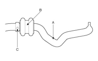
1. Install the bushing(B) on the stabilizer bar(A).
NOTE:
Bring clamp(C) of stabilizer bar(A) into contact with bushing(B).
2. Install the bracket on the bushing(B).
3. After tightening the bolts of the bushing bracket temporarily, install the bushing bracket on the opposite side.
4. Install the stabilizer bar bracket mounting bolts(A) to the sub frame.
Tightening torque :
45 - 55N.m (4.5 - 5.5kgf.m, 32.5 - 39.8lb-ft)
5. After lifting the jack which supports the sub frame, install the eight bolts and nuts of the sub frame.
Tightening torque :
140 - 160N.m (14 - 16kgf.m, 101.2 - 115.7lb-ft)
6. Install the engine mounting bolts(A,B)
Tightening torque :
50 - 65N.m (5 - 6.5kgf.m, 36.2 - 47.0lb-ft)
7. Install the connecting bolt(A) between the steering universal joint assembly and the pinion assembly.
Tightening torque :
15 - 20N.m (1.5 - 2.0kgf.m, 10.8 - 14.5lb-ft)
8. Install both sides of the connecting bolts(A) between the lower arm and the fork.
Tightening torque :
140 - 160N.m (14 - 16kgf.m, 101.2 - 115.7lb-ft)
CAUTION:
Be careful not to damage to the aluminium lower arm.
9. Install both sides of the lower arm mounting bolts(A).
Tightening torque :
100 - 120N.m (10 - 12kgf.m, 72.3 - 86.8lb-ft)
10. Install both sides of the tie rod end self-locking nuts(A).
Tightening torque :
50 - 55N.m (5 - 5.5kgf.m, 36.2 - 39.8lb-ft)
11. Install the stabilizer link(B) to the fork(A).
Tightening torque :
100 - 120N.m (10 - 12kgf.m, 72.3 - 86.8lb-ft)
12. Install the wheel and the tire(A) to the front hub(B).
Tightening torque :
90 - 110N.m (9 - 11kgf.m, 65.1 - 79.5lb-ft)
CAUTION:
Be careful not to damage the hub bolts(C) when installing the front wheel and tire(A).
13. Check the alignment.