Repair Procedures
Removal
1. Disconnect the negative terminal from the battery (A) and then wait for 30 seconds.

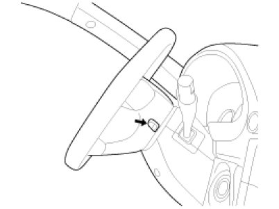
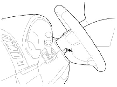
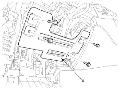
2. Loosen the bolts in the illustration.
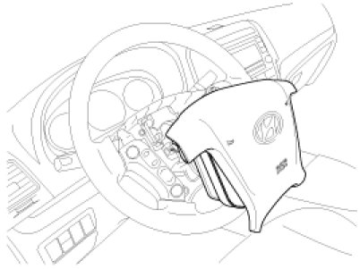
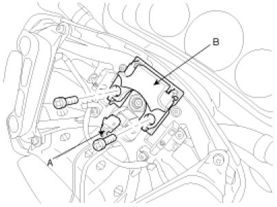
3. Disconnect the connectors (A, B) and remove the airbag module.
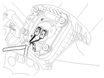
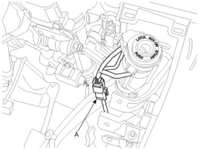
4. Disconnect the connector (A) and remove the dynamic damper (B).
5. Remove the steering wheel lock nut.
Tightening torque :
40 - 50N.m (4.0 - 5.0kgf.m, 29 - 36lb-ft)
6. After making the marks on the steering wheel and shaft for reinstallation, remove the steering wheel using a SST (09561-11001).
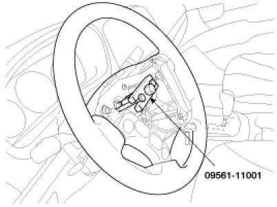
CAUTION:
Do not hammer on the steering wheel to remove it; it may damage the steering column.
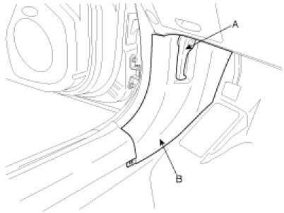
7. Remove the hood latch release handle (A) and the cowl side trim (B).
8. Remove the lower crash pad.
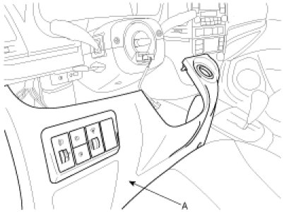
9. Remove the reinforcing panel (A).
10. Loosen the screws, and then remove the steering column upper (A) and lower shrouds (B).

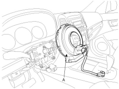
11. Disconnect the connectors from the clock spring and then remove the clock spring (A) from the steering column.
12. Remove the multifunction switch by pressing the marked portions in the illustration.

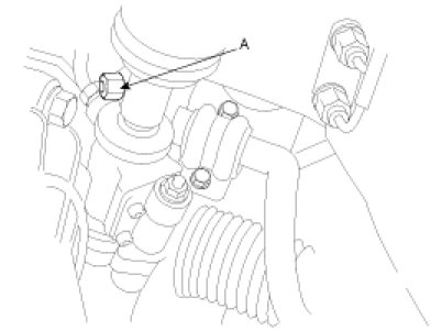
13. Loosen the bolt (A) and then disconnect the universal joint assembly from the steering gear pinion shaft.
Tightening torque :
30 - 35N.m (3.0 - 3.5kgf.m, 22 - 25lb-ft)
CAUTION:
Keep the neutral-range to prevent the damage of the clock spring inner cable when you handle the steering wheel.
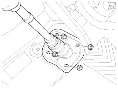
14. Loosen the dust cover mounting nuts.
Tightening torque :
4 - 6N.m (0.4 - 0.6kgf.m, 2.9 - 4.3lb-ft)
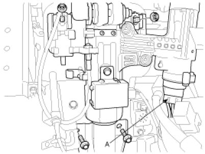
15. Disconnect the connector (A).
16. Disconnect the ignition switch connector (A) and then remove the steering column assembly by loosening the steering column mounting bolts and nuts.
Tightening torque :
13 - 18N.m (1.3 - 1.8kgf.m, 9.4 - 13.0lb-ft)
Disassembly
Key Lock Assembly
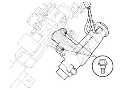
1. Make a groove on head of the special bolt (A) by using a punch.

2. Remove the key lock assembly from the steering column by loosing special bolts.
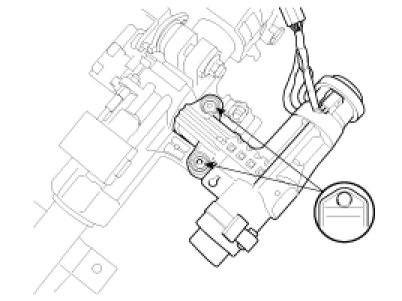
3. When reassembling the key lock assembly, loosely install new special bolts to the steering column shaft.
4. Tighten the special bolt until its head is cut off.
Universal Joint Assembly
1. Remove the universal joint assembly from the steering column assembly by loosening the bolt (A).
Tightening torque :
30 - 35N.m (3.0 - 3.5kgf.m, 22 - 25lb-ft)

2. Reassembly is the reverse of disassembly.
Inspection
1. Check the steering column shaft for damage and deformation.
2. Check connection for play, damage and smooth operation.
3. Check the joint bearing for wear and damage.
Installation
NOTE:
Before installing, apply multipurpose grease to each moving parts.
1. Installation is the reverse of removal.
CAUTION:
Align the marks on the steering wheel and shaft for reinstallation when installing the steering wheel.
When installing the clock spring, refer the RT group to prevent the damage of clock spring inner cable.