Repair Procedures
Disassembly
CAUTION:
- Use fender covers to avoid damaging painted surfaces.
- To avoid damage, unplug the wiring connectors carefully while holding the connector portion.
NOTE:
- Mark all wiring and hoses to avoid misconnection.
- Turn the crankshaft pulley so that the No.1 piston is at top dead center.
- Engine removal is required for this procedure.
WARNING:
In case of removing the high pressure fuel pump, high pressure fuel pipe, delivery pipe, and injector, there may be injury caused by leakage of the high pressure fuel. So don't do any repair work right after engine stops.
1. Remove the ladder frame.
2. Check the connecting rod end play.
3. Remove piston and connecting rod assemblies.
4. Remove crankshaft bearing cap and check oil clearance.
5. Check the crankshaft end play.
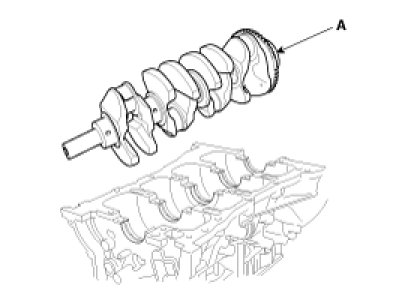
6. Lift the crankshaft (A) out of the engine, being careful not to damage journals.
NOTE:
Arrange the main bearings and thrust bearings in the correct order.
Inspection
1. Check the crankshaft bearing oil clearance.
(1) To check main bearing-to-journal oil clearance, remove the main caps and bearing halves.
(2) Clean each main journal and bearing half with a clean shop tower.
(3) Place one strip of plastigage across each main journal.
(4) Reinstall the bearings and caps, then torque the bolts.
Tightening torque :
14.7 N.m (1.5 kgf.m, 10.8 lb-ft) + 27.5 - 31.4 N.m (2.8 - 3.2 kgf.m, 20.3 - 23.1 lb-ft) + 120 - 125°
NOTE:
Do not turn the crankshaft.
(5) Remove the cap and bearing again, and measure the widest part of the plastigage.
Standard oil clearance :
0.020 - 0.038 mm (0.00079 - 0.00150 in.)
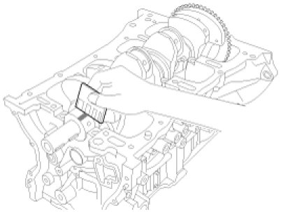
(6) If the plastigage measures too wide or too narrow, remove the upper half of the bearing, install a new, complete bearing with the same color mark (select the color as shown in the next column), and recheck the clearance.
CAUTION:
Do not file, shim, or scrape the bearings or the caps to adjust clearance.
(7) If the plastigage shows the clearance is still incorrect, try the next larger or smaller bearing (the color listed above or below that one), and check clearance again.
NOTE:
If the proper clearance cannot be obtained by using the appropriate larger or smaller bearings, replace the crankshaft and start over.
CAUTION:
If the marks are indecipherable because of an accumulation of dirt and dust, do not scrub them with a wire brush or scraper. Clean them only with solvent or detergent.
Crankshaft Bore Identification Mark
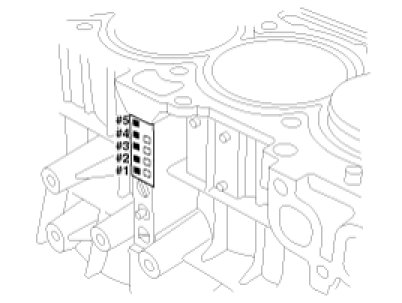
Letters have been stamped on the block as a mark for the size of each of the 5 main journal bores.
Use them, and the numbers or bar stamped on the crank (marks for main journal size), to choose the correct bearings.
Cylinder Block Specifications

Crankshaft Journal Identification Mark

NOTE:
Conform to read stamping order as shown arrow direction from #1.
Crankshaft Specifications

Crankshaft Bearing Identification Mark

Crankshaft Bearing Specifications

Selection Chart For Crankshaft Bearings

2. Check crankshaft end play.
Using a dial indicator, measure the thrust clearance while prying the crankshaft back and forth with a screwdriver.
End play
Standard : 0.07 - 0.25 mm (0.0028 - 0.0098 in.)
Limit : 0.30 mm (0.0118 in.)
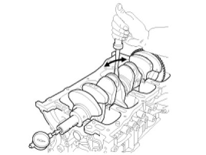
If the end play is greater than maximum, replace the thrust bearings as a set.
Thrust bearing thickness :
1.925 - 1.965 mm (0.07579 - 0.07736 in.)
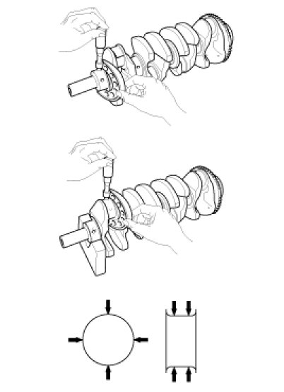
3. Inspect main journals and crank pins.
Using a micrometer, measure the diameter of each main journal and crank pin.
Main journal diameter :
51.942 - 51.960 mm (2.04496 - 2.04567 in.)
Crank pin diameter :
47.954 - 47.972 mm (1.88795 - 1.88866 in.)
Reassembly
1. Install the main bearings.
NOTE:
Upper bearings have an oil groove of oil holes; Lower bearings do not.
(1) Align the bearing claw with the claw groove of the cylinder block, push in the 5 upper bearings(A).

(2) Align the bearing claw with the claw groove of the main bearing cap, and push in the 5 lower bearings.
2. Install the thrust bearings.
Install the 2 thrust bearings(A) under the No.3 journal position of the cylinder block with the oil grooves facing outward.

3. Install the oil jet (A).
Tightening torque :
24.5 - 29.4 N.m (2.5 - 3.0 kgf.m, 18.1 - 21.7 lb-ft)

4. Place the crankshaft(A) on the cylinder block.
5. Place the main bearing caps on cylinder block.
6. Install the main bearing cap bolts.
CAUTION:
Always use new main bearing cap bolts.
NOTE:
- The main bearing cap bolts are tightened in 3 progressive steps.
- If any of the bearing cap bolts is broken or deformed, replace it.
(1) Apply a light coat of engine oil on the threads and under the bearing cap bolts.
(2) Using the SST (09221-4A000), install and uniformly tighten the 10 bearing cap bolts, in several passes, in the sequence shown.
Tightening torque :
14.7 N.m (1.5 kgf.m, 10.8 lb-ft) + 27.5 - 31.4 N.m (2.8 - 3.2 kgf.m, 20.3 - 23.1 lb-ft) + 120 - 125°

(3) Check that the crankshaft turns smoothly.
7. Check crankshaft end play.
8. Install piston and connecting rod assemblies.