Service Procedure
Replace the Audio Finisher Circuit Board located in the Cluster Lid C Assembly with the one listed in the Parts Information section as follows:IMPORTANT:
Use suitable covers to protect upholstery, carpet, etc. when performing this procedure.
Preliminary Steps:
1. Record all radio station presets.
2. Apply the parking brake and block the wheels to prevent vehicle movement.
2a. Move the A/T Shifter to the Neutral ("N") position.
3. Disconnect the negative battery cable.
Remove the All Shift Handle:

4. Re-position (push down) the A/T Shift Handle Lower Cover. You will be able to see the Retaining Clip (see Figure 1a).
5. Remove the Retaining Clip from the A/T Shift Handle (see Figure 1b).
6. Remove the A/T Shift Handle by lifting it straight up (see Figure 1c).
7. Remove the Lower Cover.
Remove A/T Console Finisher:
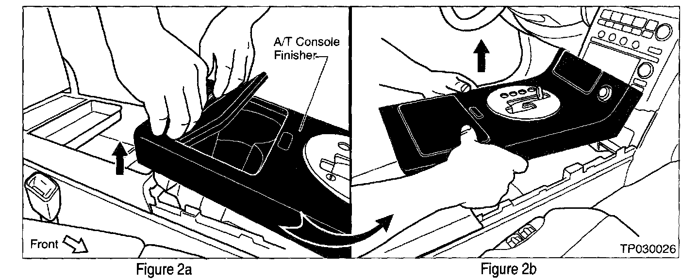
8. Carefully lift up the rear of the A/T Console Finisher to release the securing clips (see Figure 2a).
9. Then, carefully lift up the front of the A/T Console Finisher to release the remaining securing clips (see Figure 2b).
10. Disconnect the Emergency Flasher wire harness from the A/T Console Finisher.
Remove Cluster Lid Finisher:
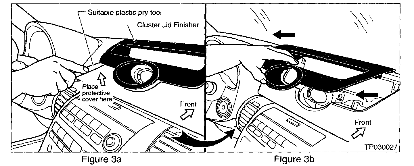
11. Using a suitable plastic pry tool, carefully pry up the Cluster Lid Finisher to release the securing clips (see Figure 3a).
NOTE:
Place a suitable protective cover (clean shop rag, a piece of Paint Guard Film ("PGF"), etc.) under the plastic pry tool to protect the instrument panel.
12. Remove the Cluster Lid Finisher from the instrument panel by pulling it rearward to release the securing clips (see Figure 3b).
Re-position the Clock Assembly:
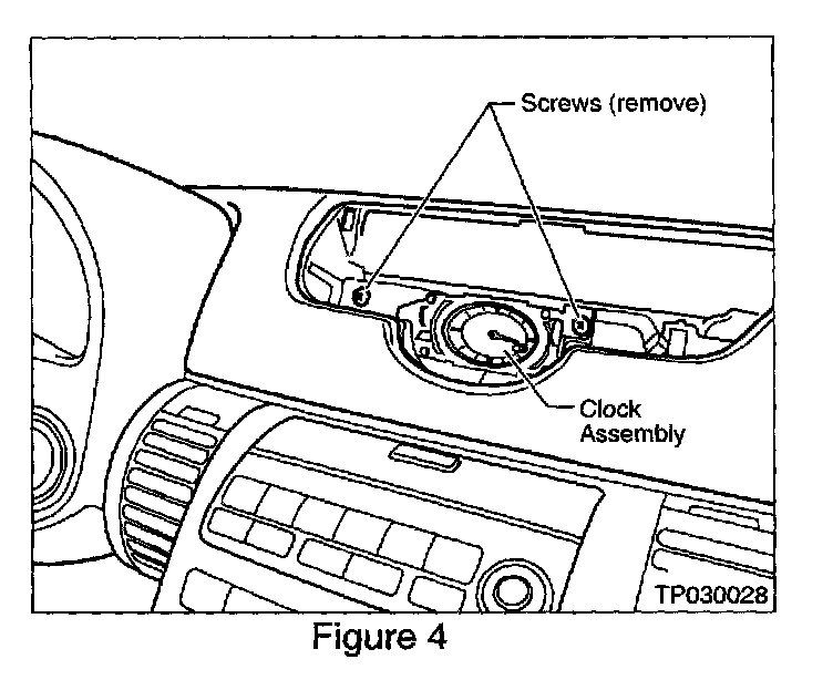
13. Remove two screws from the Clock Assembly (see Figure 4).
14. Re-position the Clock towards the left to access the "Upper Cluster Lid C" Assembly Mounting Screw (see Figure 5a).
Remove Cluster Lid C Assembly Mounting Screws:
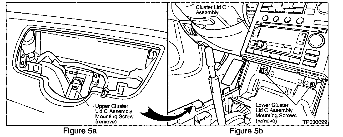
15. Remove the Cluster Lid C Assembly Mounting Screw (see Figure 5a).
16. Remove the Lower Cluster Lid C Assembly Mounting Screws (see Figure 5b).
Remove Passenger Side Door Sash Trim and Kick Panel:
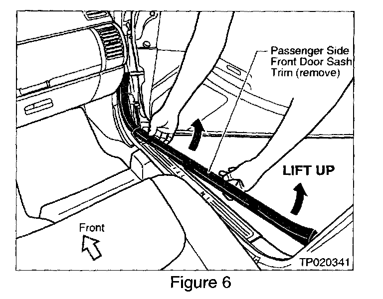
17. Carefully lift up and remove the Passenger Side Front Door Sash Trim (see Figure 6)
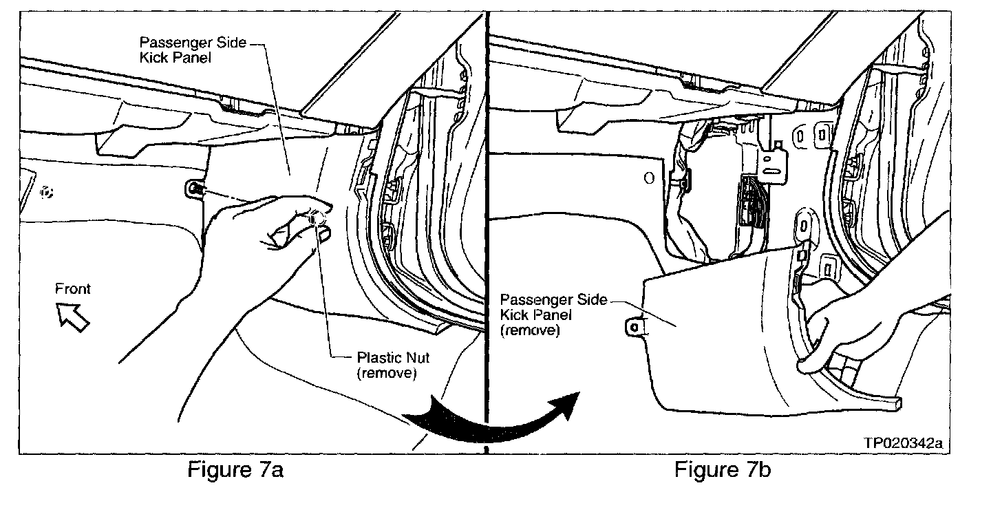
18. Remove the Plastic Nut that secures the Passenger Side Kick Panel (see Figure 7a), and remove the Kick Panel (see Figure 7b).
Re-position Glove Box Assembly:
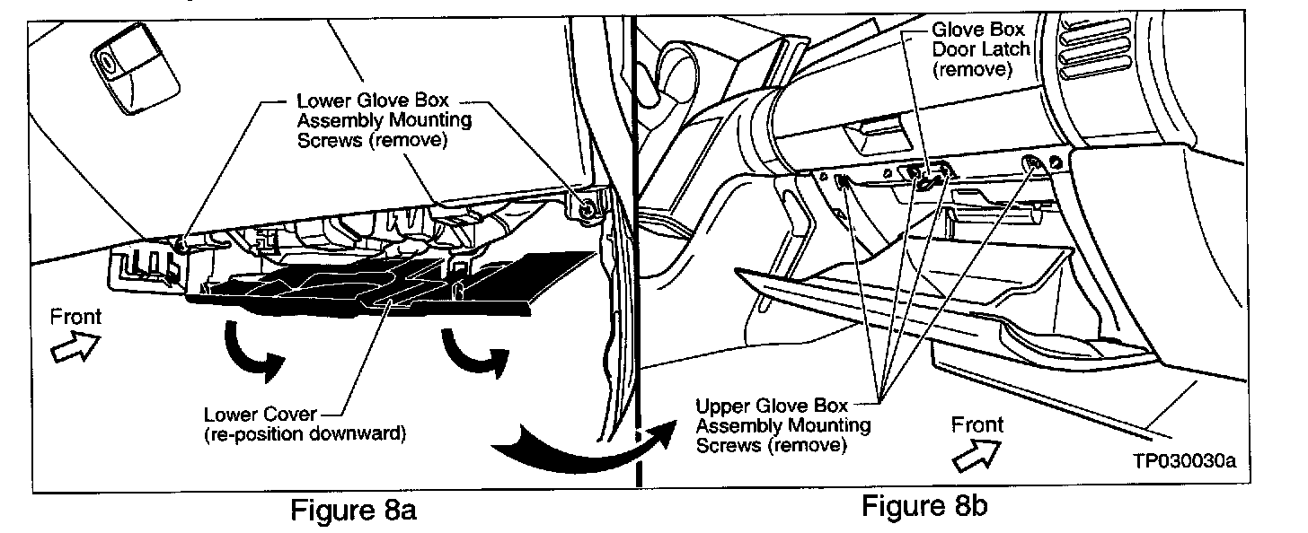
19. Re-position the Lower Cover (under the glove box) downward to access the Lower Glove Box Assembly Mounting Screws (see Figure 8a).
20. Remove the two Lower Glove Box Assembly Mounting Screws (see Figure 8a).
21. Open the glove box door and remove the four Upper Glove Box Assembly Mounting Screws and the Glove Box Door Latch (see Figure 8b).
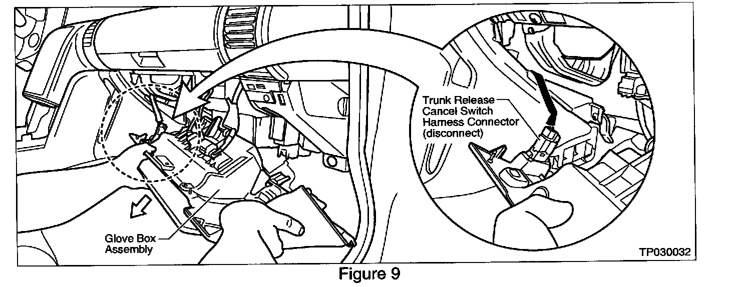
22. Move the Glove Box Assembly downward and place it on the floor (see Figure 9).
23. Disconnect the Trunk Release Cancel Switch Harness Connector (see Figure 9). This will make room for removing the RH Instrument Side Panel (covered in the next step).
Remove RH Instrument Side Panel:
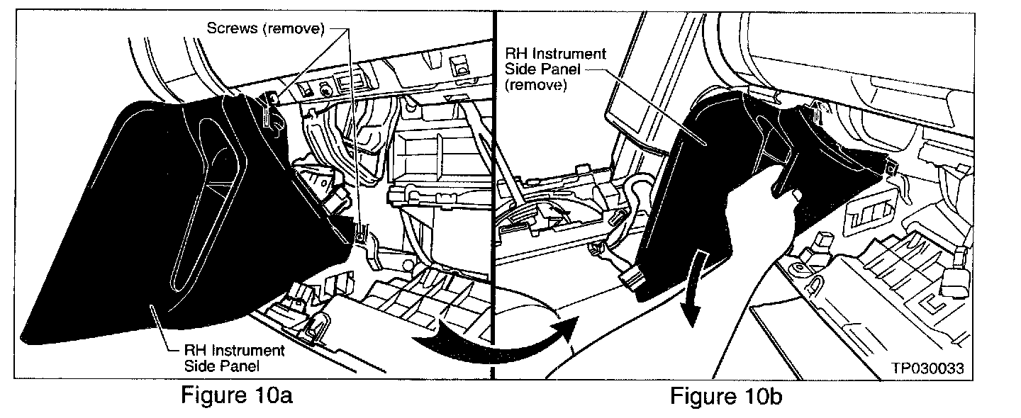
24. Remove two screws that secure the RH Instrument Side Panel (see Figure 10a).
25. Carefully remove the panel (see Figure 10b).
Re-position Driver's Side Instrument Panel Lower Cover:
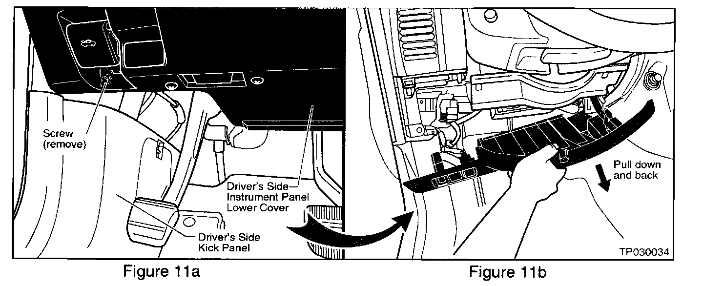
26. Remove one screw located just below the Front Hood Release Handle (see Figure 11a)
27. Carefully pull down on the Instrument Panel Lower Cover to release the securing clips (see Figure 11b).

28. If equipped: Disconnect the Automatic Temperature Control (ATC) Vent Hose and Wire Harness Connector (see Figure 12).
Remove LH Instrument Side Panel:
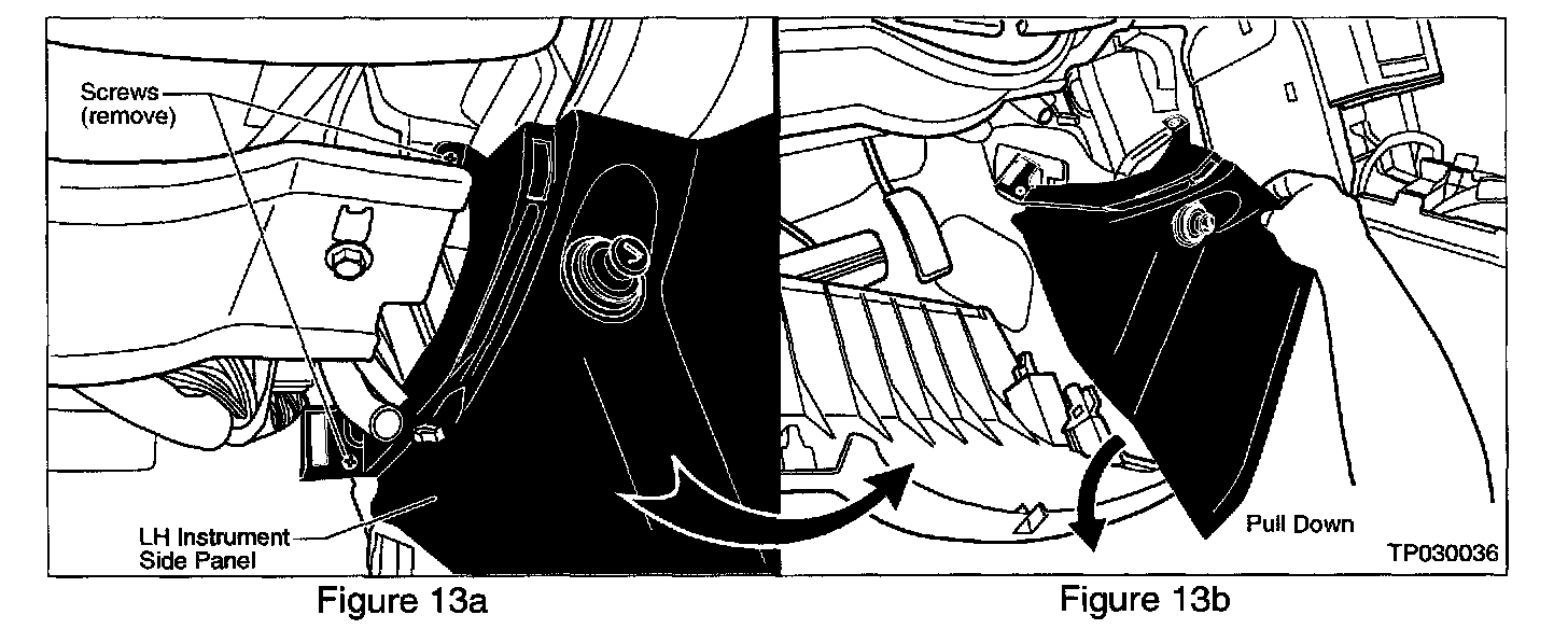
29. Remove two screws that secure the LH Instrument Side Panel (see Figure 13a).
30. Disconnect the wire harness connector for the 12V power outlet/lighter.
31. Carefully remove the panel (see Figure 13b).
Remove Cluster Lid C Assembly:
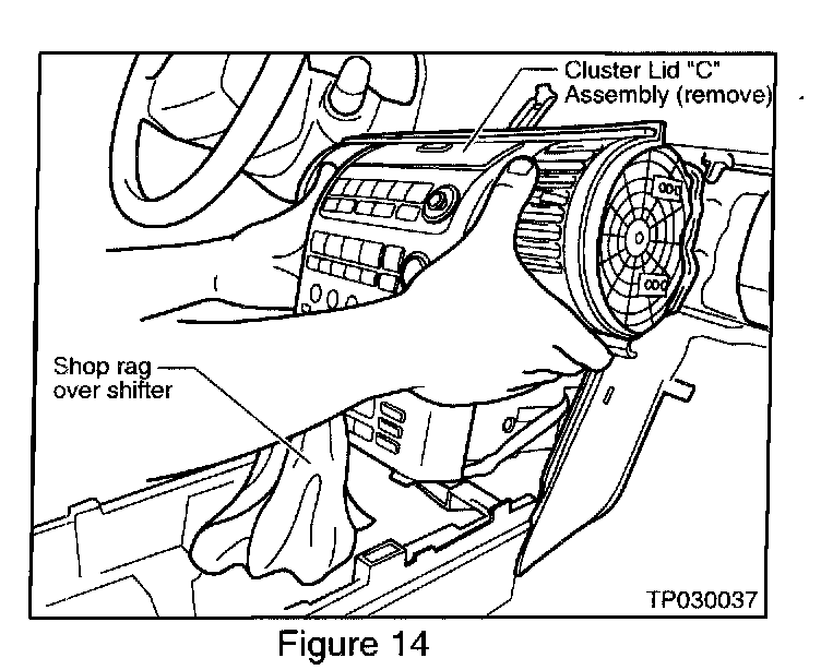
32. Place a shop rag or cloth fender cover over the A/T Shifter to protect the Cluster Lid C Assembly during removal (see Figure 14).
33. Carefully re-position the Cluster Lid C Assembly rearward to access the wire harness connectors (see Figure 14).
34. Disconnect all wire harness connectors from the Cluster Lid C Assembly.
35. Carefully remove the Cluster Lid C Assembly from the instrument panel. Then, place it face-down on a clean, soft cloth (fender cover) on your worktable to prevent damage to the face of Cluster Lid C.
Remove Audio Unit / Navigation Unit (if equipped) from Cluster Lid C Assembly:
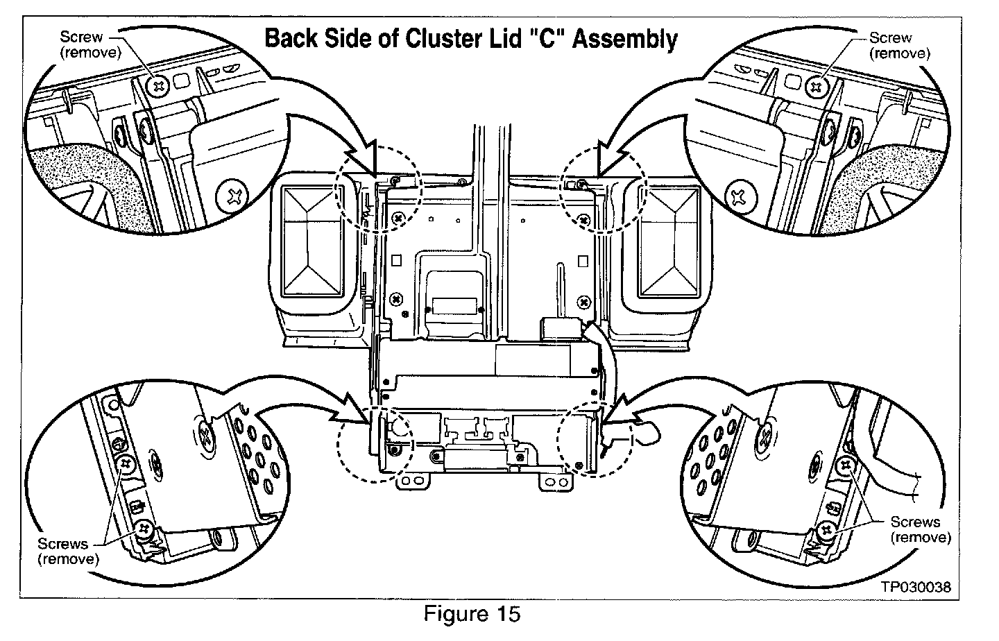
36. Remove the six screws that secure the Audio Unit / Navigation Unit (if equipped) to the Cluster Lid C Assembly (see Figure 15).
37. Disconnect the Flexible Print Circuit (FPC) from the Audio Finisher Connector as follows:
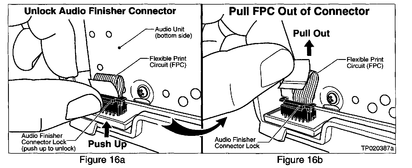
a. First: Unlock the Audio Finisher Connector Lock by lifting it upwards (see Figure 16a).
b. Second: Pull the FPC out of the Audio Finisher Connector (see Figure 16b).
38. Carefully remove the Audio Unit / Navigation Unit (if equipped) from the Cluster Lid C Assembly and place it in a safe location.
Remove Audio Finisher from Cluster Lid C:
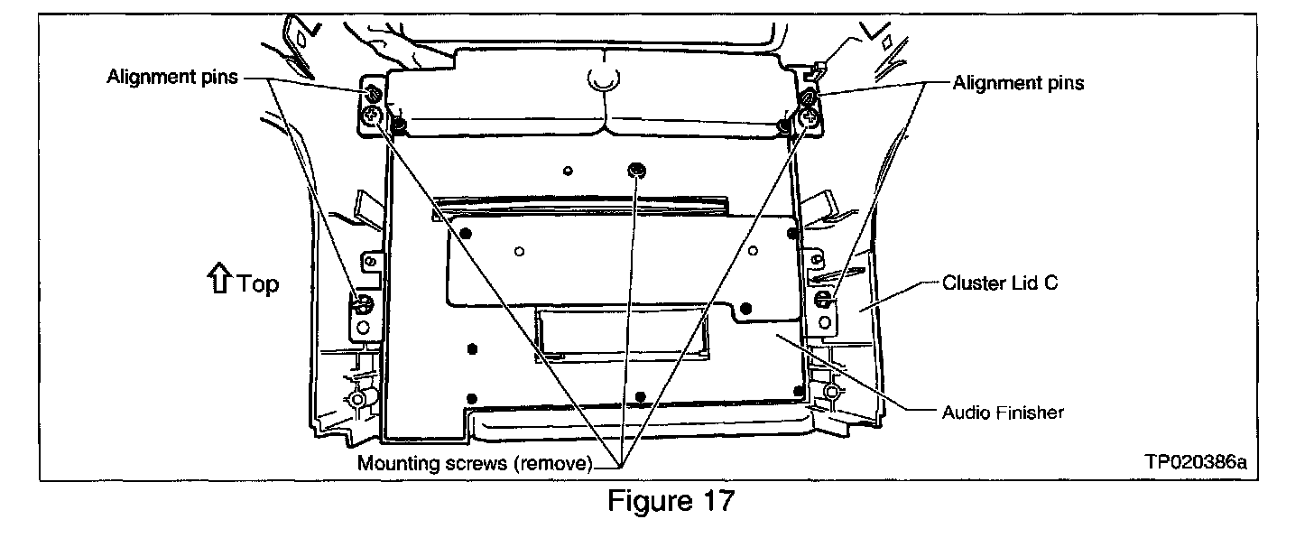
39. Remove three screws that secure the Audio Finisher to Cluster Lid C (see Figure 17).
Replace Audio Finisher Circuit Board:
40. Place the Audio Finisher face-down on a clean, soft cloth (fender cover) to prevent damage to the face of the Audio Finisher.
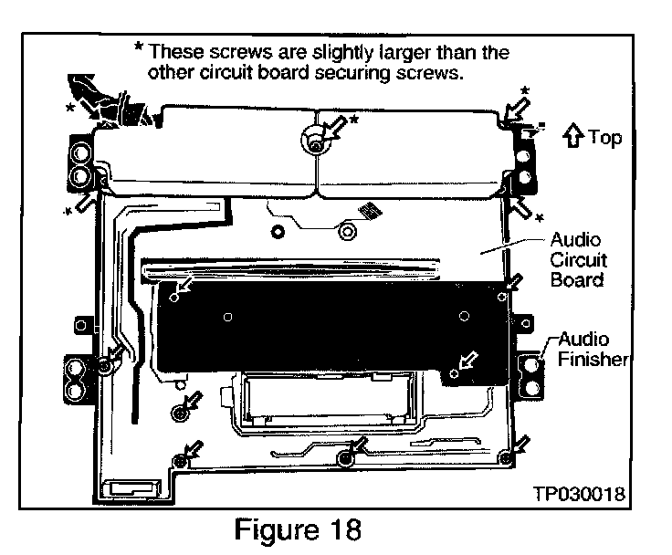
41. Remove the 13 screws that secure the Audio Circuit Board to the Audio Finisher (see Figure 18).
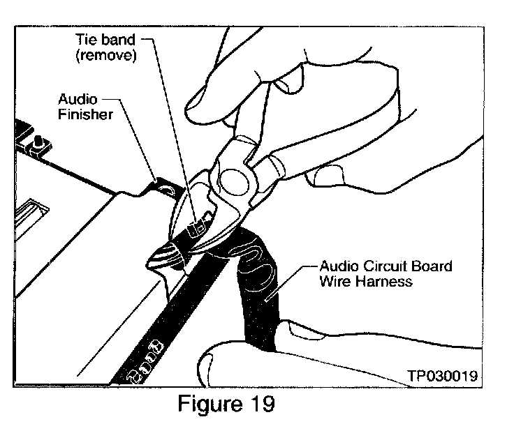
42. Carefully remove (cut off) the Tie Band that secures the Audio Circuit Board Wire Harness (see Figure 19).
IMPORTANT:
Don't cut the harness cover or the wires.
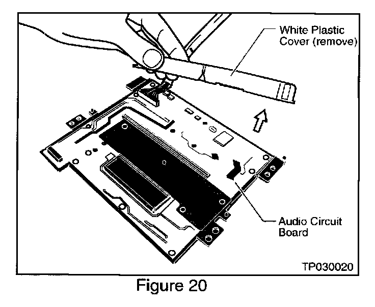
43. Remove (lift off) the White Plastic Cover from the Audio Circuit Board (see Figure 20).
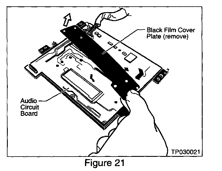
44. Remove (lift off) the Black Film Cover Plate from the Audio Circuit Board (see Figure 21).
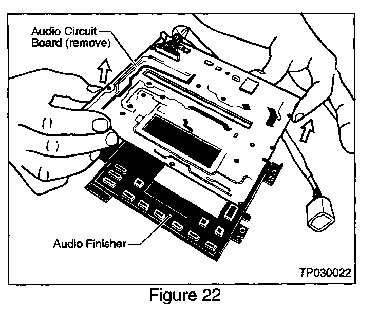
45. Remove (lift off) the Audio Circuit Board from the Audio Finisher (see Figure 22).
46. Install the new Audio Circuit Board to the Audio Finisher.
CAUTION:
Avoid Circuit Board damage:
^ Do NOT touch the circuit board surfaces or components.
^ Handle the circuit board by the edges ONLY.
47. Re-install the Black Film Cover Plate.
48. Re-install the White Plastic Cover.
49. Re-install and tighten all Audio Circuit Board securing screws.
CAUTION:
Avoid circuit board damage:
^ Do NOT overtighten the circuit board securing screws.
^ Make sure the five larger circuit board securing screws are used to secure the White Plastic Cover ONLY.
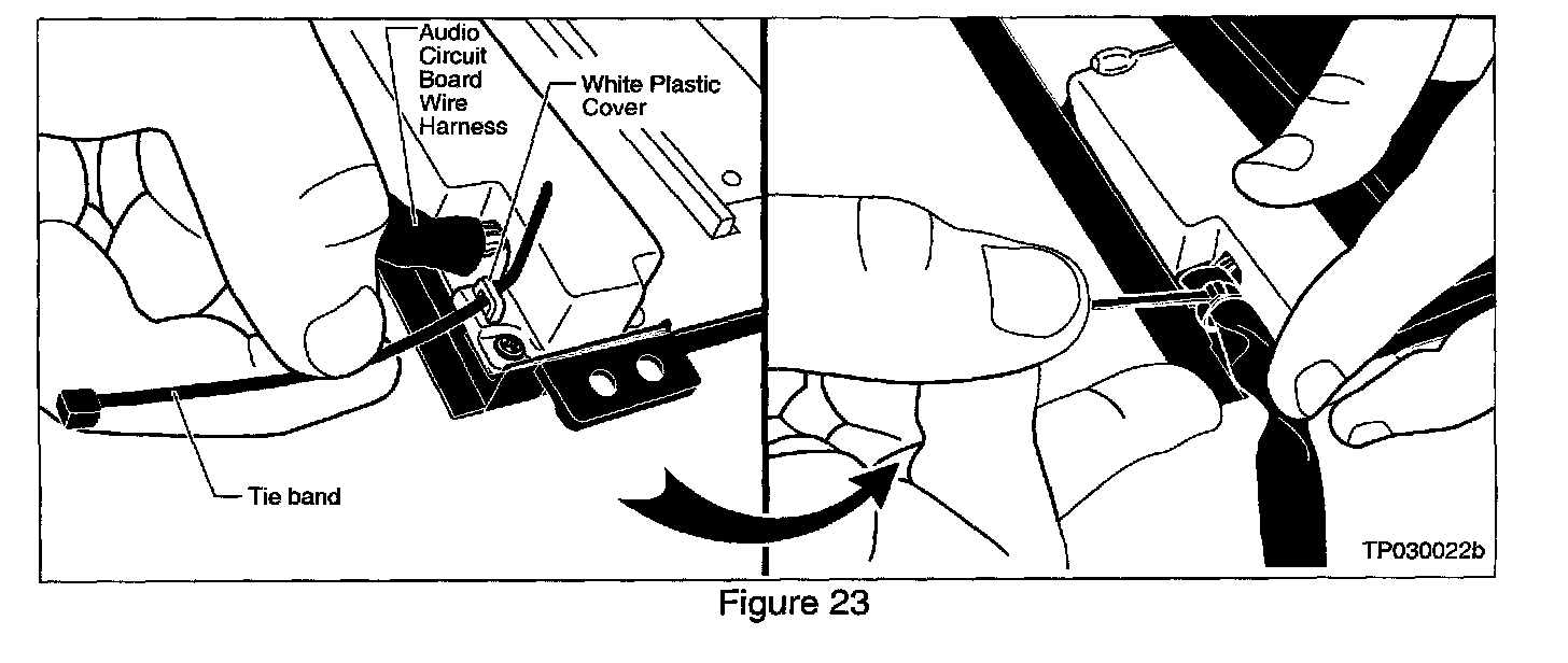
50. Secure the Audio Circuit Board Wire Harness to the White Plastic Cover using a Tie Band (see Figure 23). Then, cut oft the excess portion of the Tie Band.
Re-Assemble Removed Components:
51. Re-install the Audio Finisher to the Cluster Lid C, making sure:
^ The four alignment pins on Cluster Lid C go through the "mating holes" on the Audio Finisher (refer back to Figure 17).
^ To securely tighten the three mounting screws, being careful not to over-tighten and strip the hole threads.
52. Re-install the Audio Unit / Navigation Unit (if equipped) to the Cluster Lid C Assembly, making sure:
^ The alignment pins on Cluster Lid C go through the mating holes on the Audio Unit / Navigation Unit
^ To securely tighten the six mounting screws, being careful not to over-tighten and strip the hole threads.
^ The wire harness securing clips are correctly re-attached
53. Re-connect the Flexible Print Circuit (FPC) to the Audio Finisher Connector. Make sure the FPC is fully inserted and locked into the Audio Finisher connector.
^ Please note the following important steps when reconnecting the FPC:
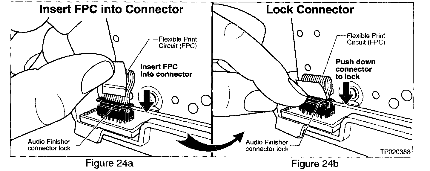
a. First, with the lock lifted up, fully insert the FPC into the Audio Finisher connector (see Figure 24a)
b. Then, lock the connector by carefully pressing it down (see Figure 24b).
54. Re-install the Cluster Lid C Assembly to the instrument panel, making sure:
^ All wire harnesses are correctly re-connected and routed to avoid pinching/chaffing.
55. Re-install the LH Instrument Side Panel, making sure:
^ The vehicle wire harness is re-connected to the 12V power supply/lighter outlet
56. Re-install the Driver's Side Instrument Panel Lower Cover, making sure:
^ The Automatic Temperature Control (ATC) Wire Harness and Vent Hose are correctly re-connected and routed to avoid pinching/chaffing.
^ All other wire harnesses are correctly re-connected and routed to avoid pinching/chaffing
57. Re-install the RH Instrument Side Panel.
58. Re-install the Glove Box Assembly, making sure:
^ The vehicle wire harness is re-connected to the Trunk Release Cancel Switch.
59. Re-install the Passenger Side Kick Panel and Front Door Sash Trim.
60. Re-install the clock.
61. Re-install the Cluster Lid Finisher.
62. Re-install the A/T Console Finisher, making sure:
^ The vehicle wire harness is re-connected to the Emergency Flasher Switch.
63. Re-install the A/T Shift Handle.
64. Re-connect the negative battery cable.
65. Re-program all radio station presets and re-set the clock.
Check Audio / Navigation (if equipped) / AC/Heater Control Functions:
^ Confirm all functions of the audio system, navigation system (if equipped), and AC/Heater system operate properly.