Engine Control - A/F Sensor Heater/Closed Loop DTCs
Classification:EC04-009
Reference:
ITBO4-012
Date:
March 2, 2004
2004 QX56; MIL "ON" WITH DTC P1031, P1051, P1148, P1168
A/F SENSOR HEATER / CLOSED LOOP
APPLIED VEHICLES:
2004 QX56 (JA60)
IF YOU CONFIRM:
A MIL ON" with the following DTC(s) stored:
^ P1031 / P1051 (A/F Sensor Heater), and/or
^ P1148 / P1168 (A/F Sensor Closed Loop Control),
ACTIONS:
A. Confirm this bulletin applies:
^ Check the Current ECM Part Number.
^ Compare your Current ECM Part Number to Chart A.
If that part number does not match one in Chart A, this bulletin does not apply. Go back to ASIST for further diagnostic and repair information.
B. Reprogram the ECM.
C. Perform A/F Sensor test to confirm proper air fuel operation.
CLAIMS INFORMATION
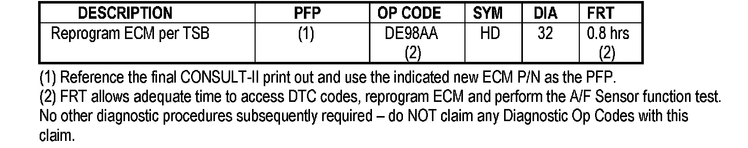
Submit a Primary Failed Part (PP) line claim using the claims coding shown.
SERVICE PROCEDURE
Step A: Confirm This Bulletin Applies

1. With CONSULT-II "ON" print the Freeze Frame data as shown.
2. Attach this printout to the Repair Order.
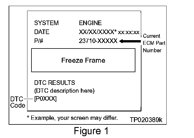
^ Figure 1 is an example of the F.F. Data printout.
^ The Freeze Frame data that you've printed contains the ECM Part Number (P/N).
^ The ECM part number will be used to see if this bulletin applies or not.
3. Check the ECM Part Number on the printout from Step 1 (Figure 1);
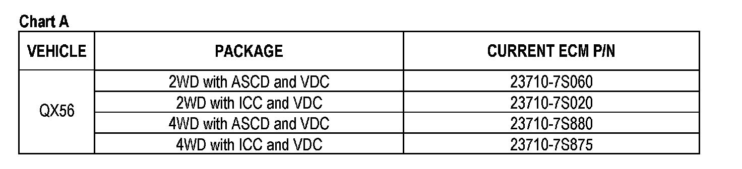
^ Compare your vehicle's ECM P/N to those shown under Current ECM P/N in Chart A.
^ If it's in that column this bulletin applies.
A. If your vehicle's ECM P/N matches a P/N in the chart above:
^ Perform ECM Reprogramming, then
^ Perform A/F Sensor Test.
B. If your vehicle's ECM P/N does not match a P/N in the chart above:
^ This bulletin does not apply. Refer to ASIST for further diagnostic and repair information.
Step B: ECM REPROGRAMMING
Vehicle ECM Reprogramming Overview
^ There are four basic steps
1. Download reprogramming data (transfer it) from ASIST into CONSULT-II.
2. Preparation steps before reprogramming.
3. Reprogram the vehicle ECM.
4. ECM Reprogramming "Wrap-up".
^ For those familiar with ECM Reprogramming please review the following steps and use them as a Quick Reference for ECM reprogramming.
Step One: Download (Transfer) Data From ASIST Into CONSULT-II
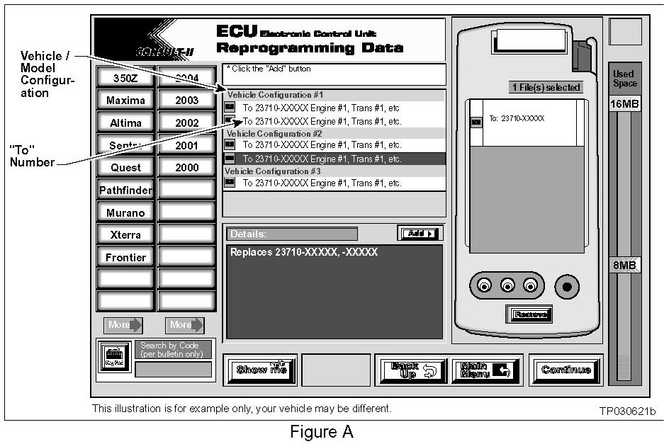
1. Select vehicle model and model year (Example: QX56 2004).
2. Select the correct reprogramming data:
a. Locate the specific Model Configuration (Example: VK56DE SAT VDC).
NOTE:
Model Configuration may include items such as engine type transmission type and vehicle options such as ASCD TCS ABS etc.
b. Select (click on) the "To" number. (Write the "To" number on the repair order.)
NOTE:
The "To" number will read: 23710-XXXXX.
3. Click on the Add button.
^ This will add the data you selected to the File(s) Selected list.
4. Write the "To" number on the Repair Order.
5. Click on Continue and follow directions to perform "data transfer" (download) from ASIST into CONSULT-II.
Step Two: Preparation for Reprogramming ECM
1. Connect a battery charger to the vehicle's battery.
^ Set the charger to a low charger rate (trickle charge).
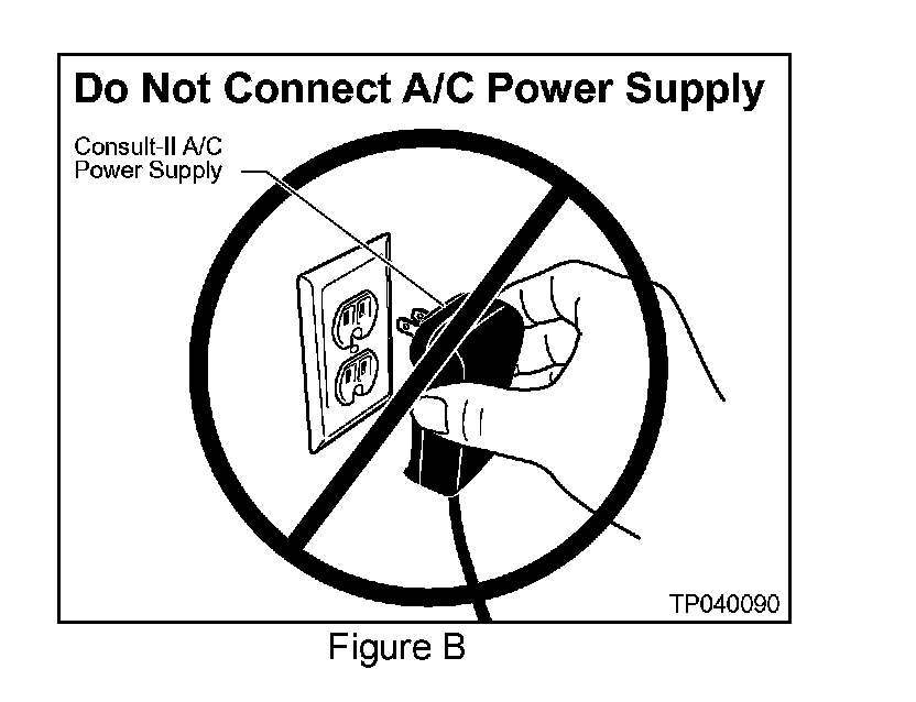
CAUTION:
For steps 2 and 3, DO NOT connect the CONSULT-II A/C Power Supply (see Figure B).
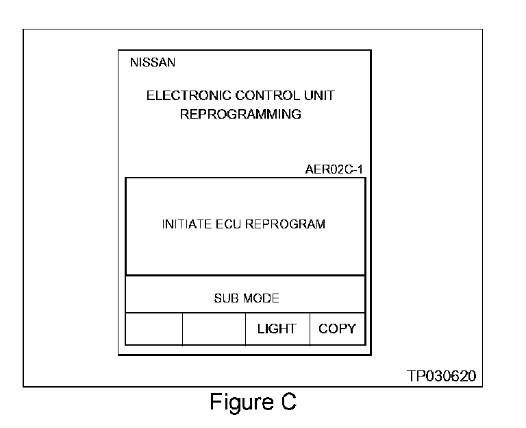
2. Press [SUB MODE] (see Figure C) then:
a. From the listed items find and select [BATTERY CHARGE].
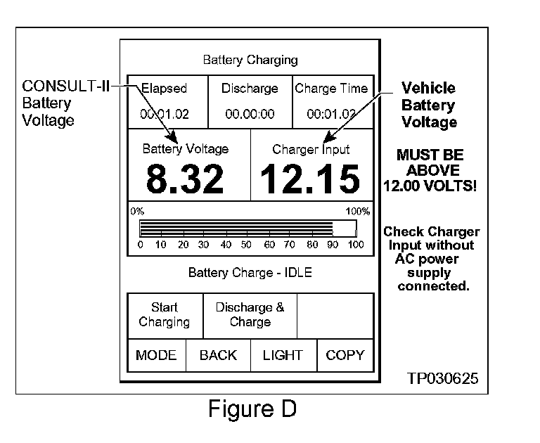
3. Check the CONSULT-II's "Charger Input" reading (see Figure D).
NOTE:
^ "Battery Voltage" is the voltage level of CONSULT-II's battery.
^ "Charger Input" is the voltage level of the vehicle's battery. (It must be above 12 volts.)
CAUTION:
If the "Charger Input" is below 12 volts:
^ A list of items to check when "Charger Input" voltage is below 12V is contained in the "ECM Reprogramming For Infiniti Vehicles" general procedure.
Step Three: Reprogram the Vehicle ECM
Step Four: "Wrap-up" After Reprogramming is Finished
1. Turn the ignition switch "OFF" and CONSULT-II "OFF".
2. Wait more than 10 seconds then;
a. Turn the ignition switch "ON" for 2 second then
b. Turn the ignition switch "OFF" again for 10 seconds (see Figure E). This will reset ECM "self learned" Data.
3. Start the engine and check the idle speed.
^ If idle speed is too low perform Idle Air Volume Learning (IAVL). See the appropriate Service Manual (ESM) for this procedure.
NOTE:
If the engine will not idle hold the engine RPM at about 2000 then slowly bring it down to an idle. IAVL can now be performed.
4. Confirm the engine is operating normally.
5. Make sure the MIL is OFF.
^ If the MIL comes ON use CONSULT-II with the Diagnostic (red/white) Card to erase any DTCs that may have stored during the reprogramming procedure.
Step C: Perform A/F Sensor Test
1. Use CONSULT-II DATA MONITOR to view;
^ Engine Speed and
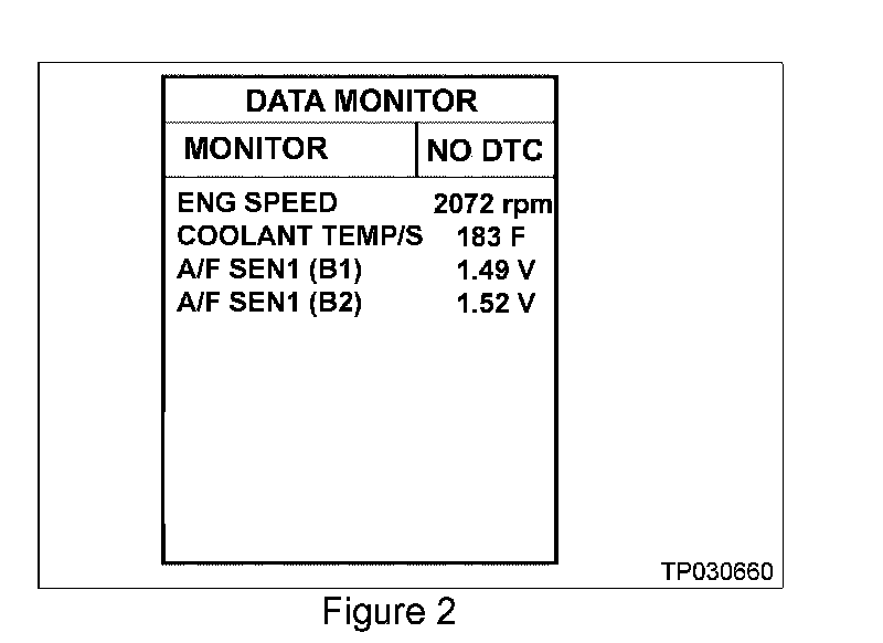
^ A/F Sensor voltage (see Figure 2).
2. Hold the engine speed at about 2000 rpm no-load for 2 minutes.
^ This will create a stable condition for step 3 (below).
3. Observe A/F SEN1 (B1) and A/F SEN1 (B2) voltage for 30 seconds while holding 2000 rpm no-load.
a. A/F sensor voltages should remain (most of the time) between 1.37 and 1.57 volts.
^ If the engine rpm is held constant voltage will fluctuate but should remain in this range.
b. If most of the time the A/F sensor voltages are out of this range:
^ The vehicle has an additional incident.
^ This bulletin does not have repair information for an A/F Sensor or Fuel Management System incident.
^ Use the appropriate Service Manual (ESM) section EC (P1031 / P1051 / P1148 / P1168) to further diagnosis and repair the additional incident.

Disclaimer