Catalytic Converter: Service and Repair

EXHAUST MANIFOLD AND THREE WAY CATALYST
REMOVAL
WARNING: Perform the work when the exhaust and cooling system have cooled sufficiently.
1. Remove air duct and resonator assembly (inlet).
2. Drain engine coolant from the radiator.
3. Remove engine undercover with power tool.
4. Remove the radiator and radiator hoses.
5. Remove drive belts.
6. Remove the air fuel ratio A/F sensors (right bank, left bank).
^ Follow steps to remove each air fuel ratio A/F sensors.
a. Remove engine room cover with powertool.
b. Remove harness connector of each air fuel ratio A/F sensors, and harness from bracket and middle clamp.
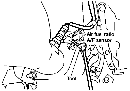
c. Remove the air fuel ratio A/F sensors from both left and right exhaust manifolds using Tool.
Tool number: KV101 14400 (J-38356)
CAUTION:
^ Be careful not to damage the air fuel ratio A/F sensors
^ Discard any air fuel ratio A/F sensor which has been dropped from a height of more than 0.5 m (19.7 inch) onto a hard surface such as a concrete floor; replace with a new one.
7. Remove front cross bar.
8. Remove exhaust manifold (left bank) in steps.
a. Remove exhaust front tube with power tool.
b. Remove the exhaust manifold cover.
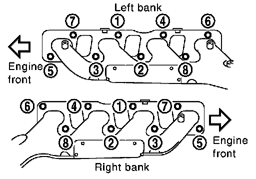
c. Loosen nuts in reverse order of illustration with power tool.
d. Remove exhaust studs from positions 2, 4, 6, 8 and remove left exhaust manifold
9. Remove exhaust manifold (right bank) in steps.
a. Remove exhaust front tube with power tool.
b. Remove oil level gauge guide.
c. Remove the exhaust manifold cover.
d. Loosen nuts in reverse order of illustration with power tool.
e. Remove exhaust studs from positions 2, 4, 6, 8 and remove right exhaust manifold.
INSPECTION AFTER REMOVAL
Surface Distortion
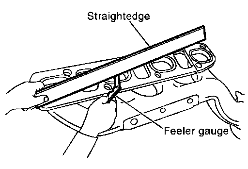
^ Use a reliable straightedge and feeler gauge to check the flatness of each exhaust manifold flange surface.
Flatness limit : 0.3 mm (0.012 inch)
^ If it exceeds the limit, replace exhaust manifold.
INSTALLATION
Installation is in the reverse order of removal paying attention to the following:
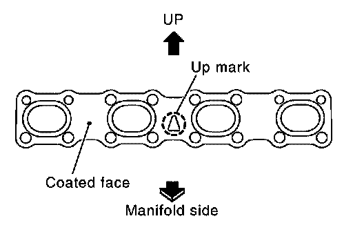
^ Install new exhaust manifold gasket with the top of the triangular up mark on it facing up and its coated face (gray side) toward the exhaust manifold side.

^ Install exhaust manifold.
^ Tighten exhaust manifold nuts in numerical order shown.
^ Before installing a new air fuel ratio A/F sensors, clean exhaust system threads using Tool. oxygen sensor thread cleaner (commercial service tool: J-43897-18 or J-43897-12), and apply anti-seize lubricant.
Tool number
: ( - ) J-43879-12
: ( - ) J-43897-18
CAUTION:
^ Do not over tighten the air fuel ratio A/F sensors . Doing so may cause damage to the sensor, resulting in the MIL coming on.