Compressor Clutch: Service and Repair
Removal and Installation of Compressor ClutchREMOVAL
Overhaul
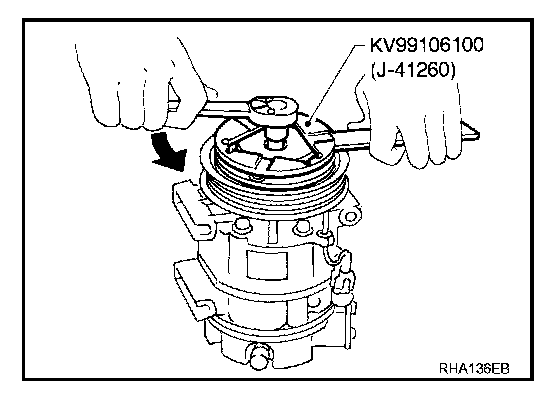
1. When removing center bolt, hold clutch disc with a wrench.
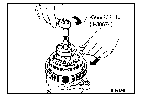
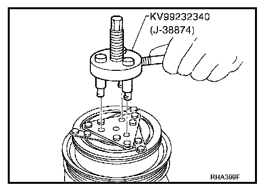
2. Remove clutch disc using clutch disc puller.
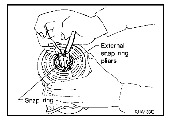
3. Remove snap ring using external snap ring pliers.
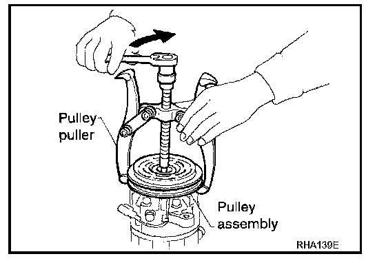
4. Position center pulley puller on the end of the driveshaft, and remove pulley assembly using any commercially available pulley puller.
To prevent the pulley groove from being deformed, the puller claws should be positioned at the edge of the pulley assembly.
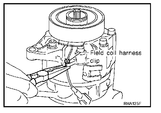
5. Remove field coil harness clip using a pair of pliers.
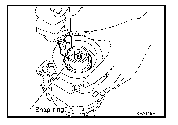
6. Remove snap ring using external snap ring pliers.
Inspection
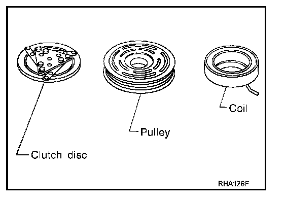
Clutch disc
If the contact surface shows signs of damage due to excessive heat, replace clutch disc and pulley.
Pulley
Check appearance of the pulley assembly. If contact surface of pulley shows signs of excessive grooving, replace clutch disc and pulley. The contact surfaces should be cleaned with a suitable solvent before reinstallation.
Coil
Check coil for loose connection or cracked insulation.
INSTALLATION
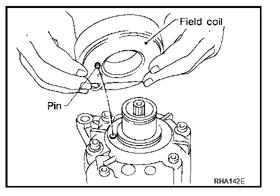
1. Install field coil.
Be sure to align coil's pin with hole in the compressor's front head.
2. Install field coil harness clip using a screwdriver.
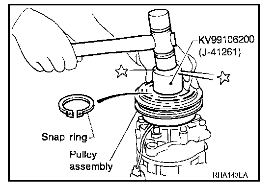
3. Install pulley assembly using installer and a hand press, and then install snap ring using snap ring pliers.
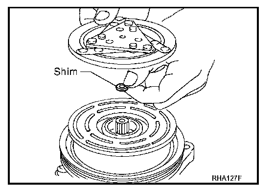
4. Install clutch disc on drive shaft, together with original shim(s). Press clutch disc down by hand.
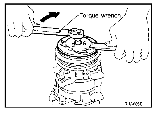
5. Using a holder to prevent clutch disc rotation.
Tightening torque : 14 Nm (1.4 kg-m, 10 ft-lb)
After tightening the bolt, make sure the pulley rotates smoothly.
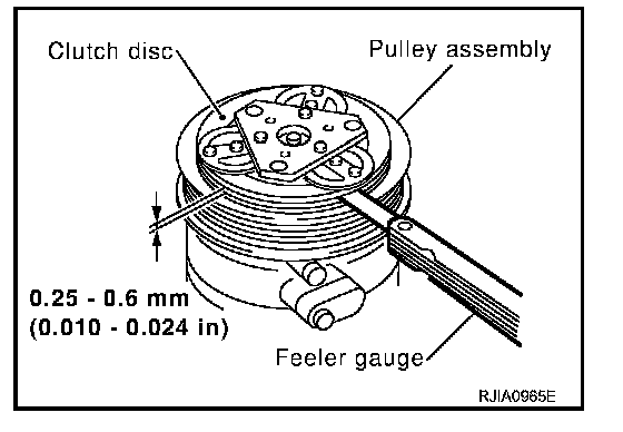
6. Check clearance around the entire periphery of clutch disc.
Disc to pulley clearance : 0.25 - 0.6 mm (0.010 - 0.024 in)
If the specified clearance is not obtained, replace adjusting spacer and readjust.
Break-In Operation
When replacing compressor clutch assembly, always carry out the break-in operation. This is done by engaging and disengaging the clutch about thirty times. Break-in operation raises the level of transmitted torque.