Brake Signal Circuit
BRAKE SIGNAL CIRCUIT
CONSULT-II Reference Value
Diagnostic Procedure
1. CHECK CAN COMMUNICATION LINE
Perform the self-diagnosis. Refer to SELF-DIAGNOSTIC RESULT MODE, AT104. Diagnostic Procedure without CONSULT-II. Without Scan Tool
Is a malfunction in the CAN communication indicated in the results?
YES >> Check CAN communication line. Refer to DTC U1000 CAN COMMUNICATION LINE. Transmission Control Systems
NO >> GO TO 2.
2. CHECK STOP LAMP SWITCH CIRCUIT
With CONSULT-II

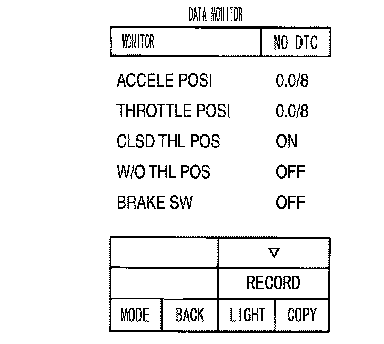
1. Turn ignition switch ON. (Do not start engine.)
2. Select ECU INPUT SIGNALS in DATA MONITOR mode for A/T with CONSULT-II.
3. Read out ON/OFF switching action of the BRAKE SW.
OK or NG
OK >> INSPECTION END
NG >> GO TO 3.
3. CHECK STOP LAMP SWITCH

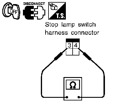
Check continuity between stop lamp switch harness connector terminals. Refer to Wiring Diagram AT-NON DTC.
Check stop lamp switch after adjusting brake pedal-refer to BRAKE PEDAL.
OK or NG
OK >> INSPECTION END _
NG >> Check the following. If NG, repair or replace damaged parts
^ Harness for short or open between battery and stop lamp switch.
^ Harness for short or open between stop lamp switch and combination meters.