DTC 45
Fig. 15 Oxygen sensor circuit identification:

1. Check continuity between control unit harness connector terminal No. 30 and oxygen sensor harness connector terminal, Fig. 15.
2. If continuity is not present, repair or replace harness assembly. If continuity is present, proceed to step 3.
3. Test oxygen sensor as follows:
a. Disconnect sensor electrical connector.
Fig. 16 Connecting oxygen sensor test wire:
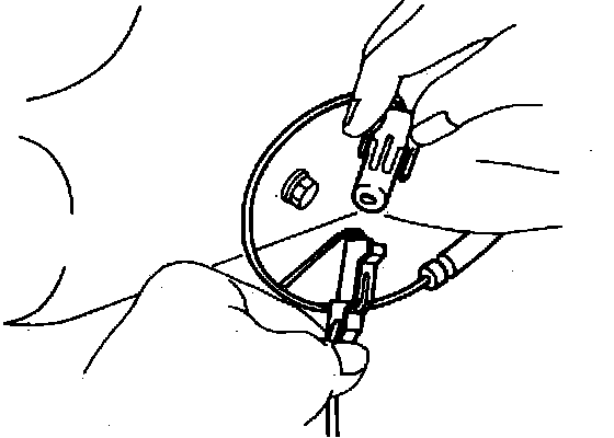
b. Insert suitable wire into side connector, so that a part of the wire is directly exposed, Fig. 16, then reconnect electrical connector.
c. Set circuit tester to the measuring range of approximately 2 volts, then connect positive lead of tester to exposed wire and negative lead to ground.
d. Start engine and check reading of tester when engine speed is suddenly increased. Normal operation of oxygen sensor is indicated when the tester needle deflects within the range of .5 to .8 volts.