Checking ECM Unit Power Supply Circuit
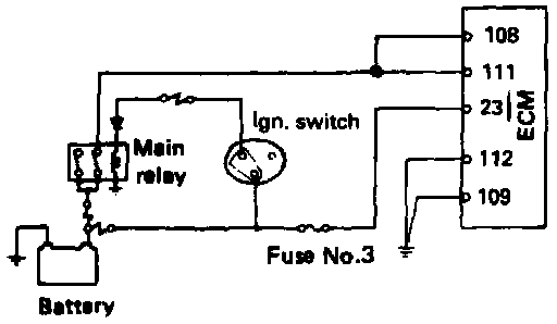
WIRING DIAGRAM
Confirmation
1. Disconnect ECM connectors.
2. Turn key to ON position.
3. Check that power voltage is present at connector terminals (108), (111) and (23).
4. Check that continuity exists between the connector terminals (109), (112) and ground.
Inspection and Correction
1. When power voltage is not present at terminals (108), (111) and (23).
Check the main relay, ignition switch, fuses, fusible link wires and related circuits and correct or replace the parts as necessary.
2. If the digital multimeter does not indicate continuity across the terminals (109), (112) and ground, correct or replace grounding cable.
3. Connect the ECM connectors properly.