EGR Valve: Description and Operation
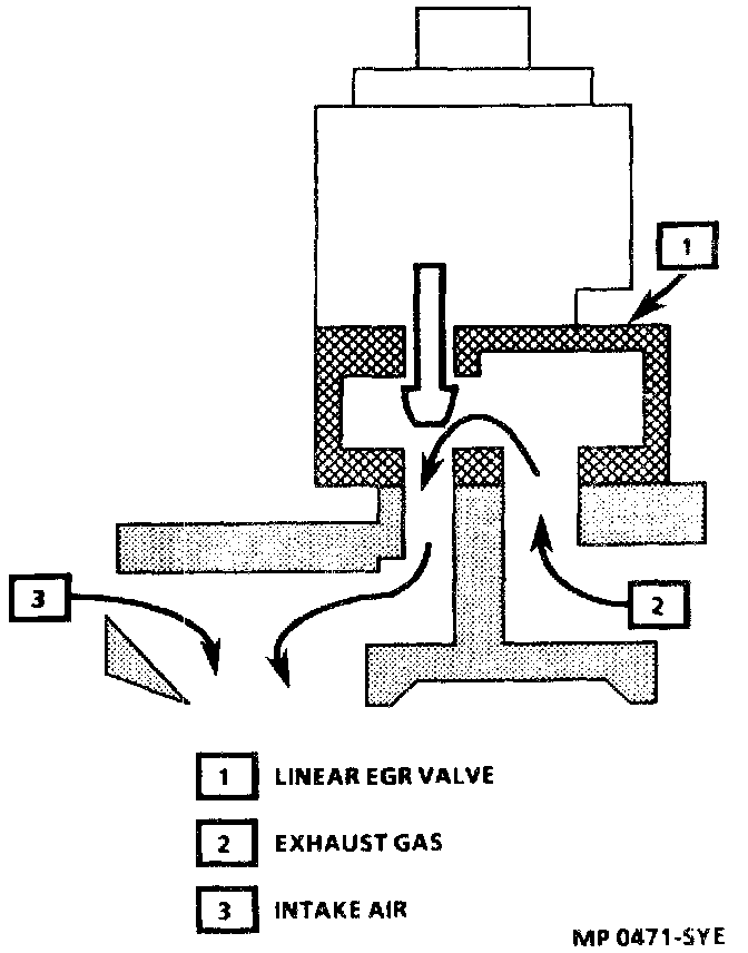
Figure 9A-1-Exhaust Gas Flow:
General Description
The linear Exhaust Gas Recirculation (EGR) valve is operated exclusively by Powertrain Control Module (PCM) command. The PCM monitors various engine parameters:
- Throttle Position (TP) sensor.
- Manifold Absolute Pressure (MAP).
- Engine Coolant Temperature (ECT) sensor.
- EGR Pintle position sensor.
Output messages are then sent to the EGR system indicating the proper amount of exhaust gas recirculation necessary to lower combustion temperatures. This electronic metering of exhaust gas is ten times faster than vacuum-operated models and offers improved diagnostic capabilities as well.
Exhaust Gas Recirculation (EGR) System Circuit Description:
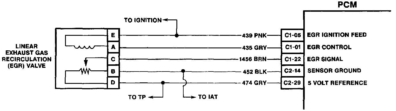
Positioned at he top of the linear EGR assembly are 5 terminals.
Figure 9A-2 - Linear EGR Valve Cross-Section:
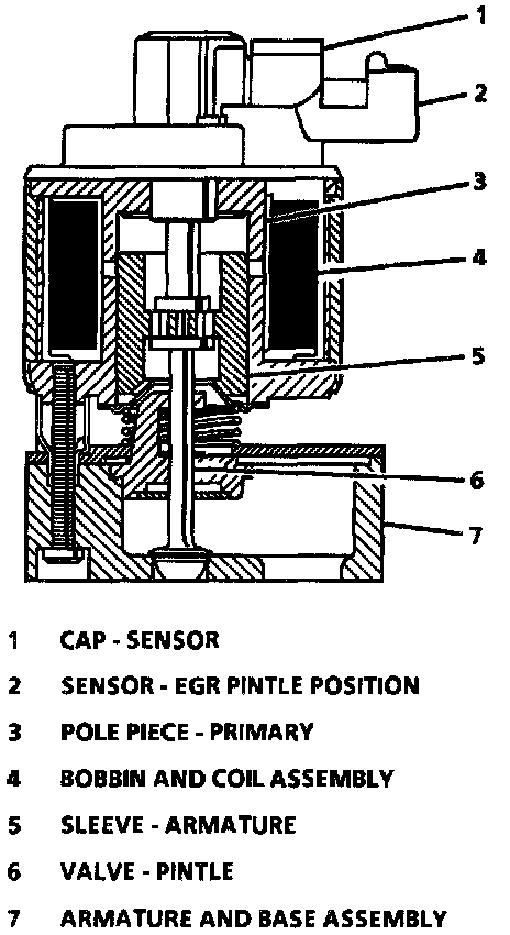
The solenoid (bobbin and coil) assembly is energized by 12 volt current which enters the valve through an electrical connector (terminal "E"), then flows through the solenoid assembly to the control module and creates an electromagnetic field. This field causes the armature assembly to be pulled upward, lifting the pintle a variable amount off the base.
The exhaust gas then flows from the exhaust manifold (through the orifice) to the intake manifold. The height of the pintle is read by the pintle position sensor, and the control module closes the loop on desired position versus actual position read, changing the pulse width modulated command to the solenoid accordingly, until the actual pintle position equals the desired pintle position.
The linear EGR valve is unique in that the control module continuously monitors pintle height and continuously corrects it in order to obtain accurate flow, making linear EGR a "Closed Loop" system.
When the solenoid is de-energized (control module breaks the circuit), the pintle is sealed against the orifice, blocking exhaust flow to the intake manifold.