Fuel Injector: Service and Repair
CAUTION:- Always remove the fuel pressure regulator to drain excess fuel, and to prevent fuel from entering engine cylinders when fuel injectors are removed for service. Flooded cylinders could result in engine damage.
- Use care in removing fuel injectors to prevent damage to the electrical connector pins on the injector and the nozzle. The fuel injector is serviced as a complete assembly only. Since it is an electrical component, do not soak it in cleaner.
Figure 4C-8 Upper And Lower Intake Components:

Legend:
1. Manifold Assembly - Upper
2. Stud - Upper Inlet Manifold
3. Harness Assembly - EGR Valve and Fuel Pressure Regulator Vacuum
4. Seal - MAP sensor
5. Sensor- Manifold Absolute Pressure (MAP)
6. Bolt - MAP Sensor Attaching
7. Fitting and Washer Assembly - EGR Transfer Tube
8. Valve Assembly - Idle Air Control (IAC)
9. Screw - AC Valve Attaching
10. 0-Ring - IAC Valve
11. Tube Assembly - EGR transport
12. Bolt - Upper Inlet Manifold
13. Gasket - Upper Inlet Manifold
14. Fitting - Power Brake
15. 0-Ring - Fuel Inject or Upper
16. Injector Assembly - (Bottom Feed) SFI Fuel injectors
17. 0-Ring - Fuel Injector Lower
18. Screw - Fuel Pressure Connection Fitting
19. Bracket - Fuel Pressure Connection Fitting
20. Fitting - Fuel Feed
21. 0-Ring - Fuel Feed Pipe Fitting
22. 0-Ring - Fuel Feed Pipe Fitting
23. Pipe Assembly - Fuel Feed
24. Manifold Assembly - Lower
25. Retainer - Injectors
26. Screw - Injectors Retainer Attaching
27. Screw - TP Sensor Attaching
28. Sensor - Throttle Position (TP)
29. Pipe Assembly - Fuel Return
30. 0-Ring - Fuel Return Pipe Fitting
31. Screen - Filter (if so equipped)
32. 0-Ring - Fuel Pressure Regulator
33. Screw - Fuel Pressure Regulator Attaching
34. Regulator Assembly - Fuel Pressure
Figure 4C-10 - Accelerator Cam Splash Shield:
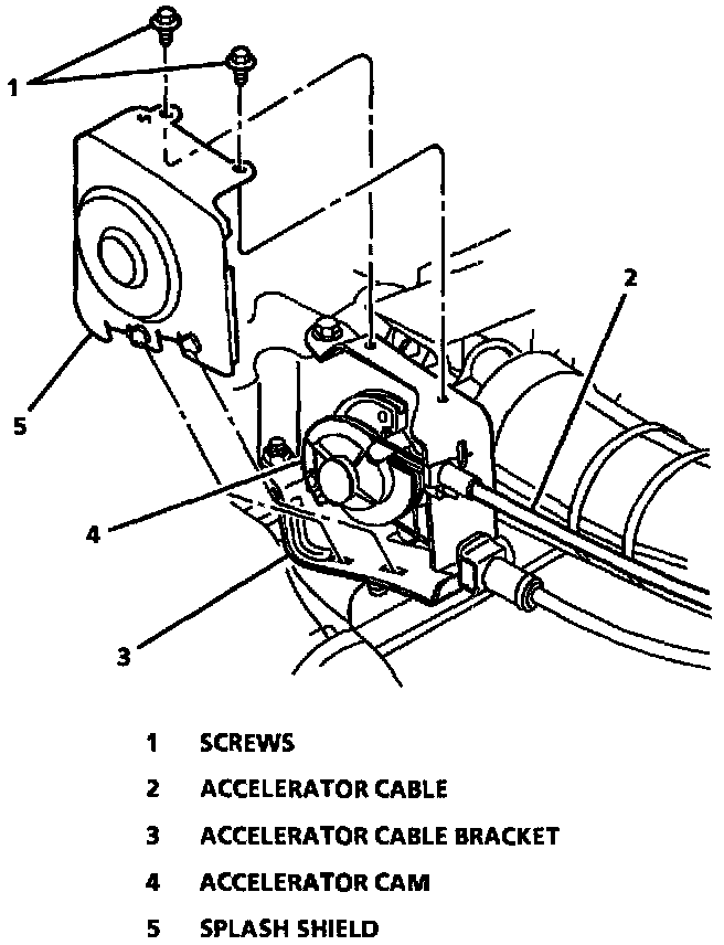
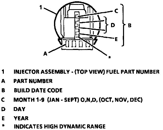
Figure 4C-12 - Injector Part Number Location:
REMOVE OR DISCONNECT
1. Relieve fuel system pressure.
2. Disconnect negative battery cable.
3. Upper manifold assembly.
CAUTION: To reduce the chance of personal injury, cover regulator and fuel line fittings with a shop towel before disconnecting to catch any fuel that may leak out. Place the towel in an approved container after disconnect is completed.
4. Fuel return line retaining bracket nut.
5. Fuel return line retaining bracket - Move return line away from regulator.
6. Pressure regulator assembly.
NOTE:
- To prevent damage to the fuel injector retaining bracket and/or fuel injectors, do not try to remove the fuel injectors by lifting up the fuel injector retaining bracket while the fuel injectors still are installed in bracket slots.
- Do Not attempt to remove bracket without first removing fuel pressure regulator.
7. Injector retainer bracket attaching screws.
8. Injector retainer bracket.
- Carefully slide bracket off to clear injector slots and regulator.
9. Electrical injector connectors.
CAUTION: To reduce the risk of fire and personal injury, verify that the lower (small) 0-ring of each injector does not remain in the lower manifold If the 0-ring is not removed with the injector the replacement injector, with new 0-rings, will not seat properly in the injector socket and could cause a fuel leak
10. Fuel injectors - Discard 0-ring seals.
IMPORTANT: Each injector is calibrated for a specific flow rate. When replacing fuel injectors, order replacements with the identical part number as the old injectors.
NOTE: Cover injector sockets to prevent dirt and other contaminants from entering open fuel passages.
INSTALL OR CONNECT
1. Lubricate new injector 0-ring seals with clean engine oil, and install on injector assembly.
2. Bottom feed Sequential injector assembly into lower manifold injector socket with electrical connectors facing inward.
3. Injector retainer bracket.
- Carefully install bracket so that injector retaining slots and regulator are aligned with bracket slots.
4. Electrical injector connectors.
5. Pressure regulator assembly.
6. Injector retainer bracket attaching screws.
7. Upper manifold assembly.
Tighten Injector retainer bracket attaching screws to 3.5 Nm (31 in. lbs.).
8. Accelerator cable bracket with attaching bolts/nuts.
Tighten
- Accelerator cable bracket nut to 30 Nm (22 ft. lbs.).
- Accelerator cable bracket bolts to 25 Nm (18 ft. lbs.).
9. Tighten fuel filler cap.
10. Negative battery terminal.
11. Air intake duct.
INSPECT
Turn ignition switch to the "ON" position for two seconds, then turn to the "OFF" position for ten seconds. Again turn to the "ON" position and check for fuel leaks.
IMPORTANT: The hardware used to attach the upper manifold Throttle Position (TP) sensor, Idle Air Control (IAC) valve, MAP sensor, power brake fitting, and the lower manifold pressure regulator and injector bracket attaching hardware are coated with thread-locking adhesive. If any these parts are removed for service, inspect the attaching screw threads. There should be enough thread-locking material (adhesive or compound) on the threads to ensure proper relocking. If not, clean the threads and apply a thread locking adhesive to the threads before reassembly. Replacement screws are included in the service screw assortment package. New attaching hardware is included in the service packages.