Transmission Disassembly
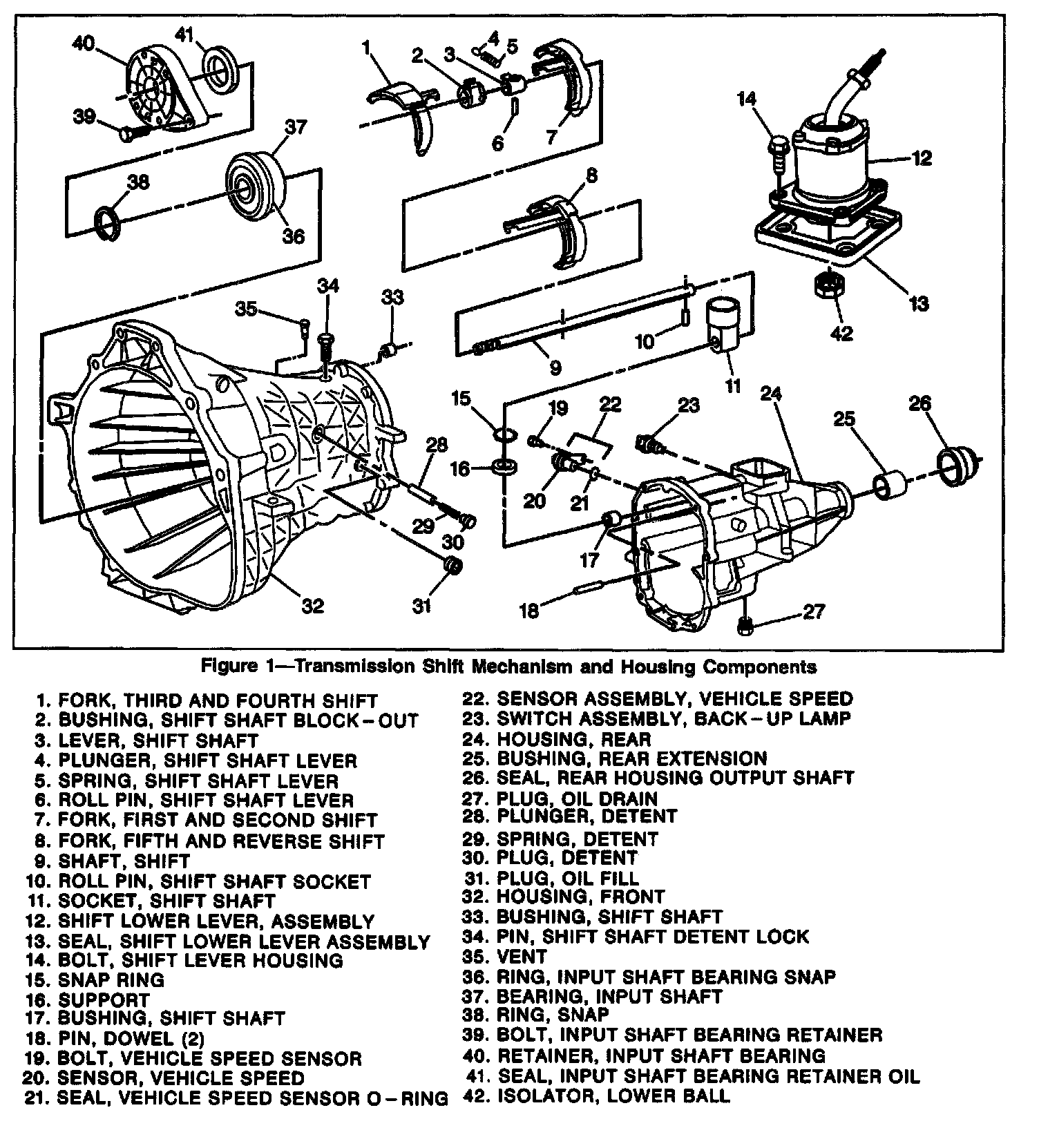
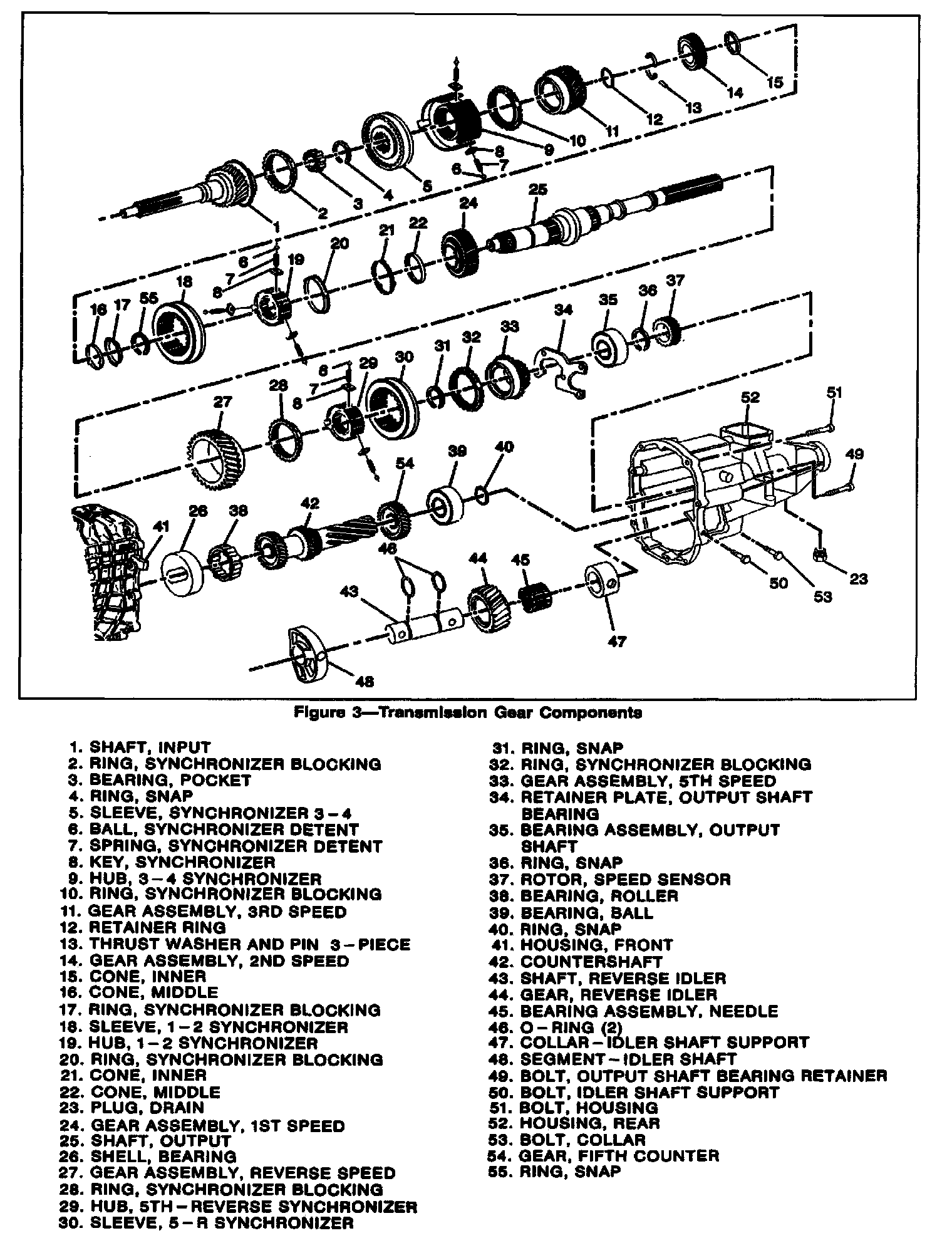
Tool Required:
J 36509 Detent Spring Plug Remover
J 23907 Slide Hammer
J 8105 Gear Puller
J 21427-01 Speedometer Gear Puller Adapter
J 22912-01 Gear and Bearing Separator Plate Hydraulic Press
Disassemble
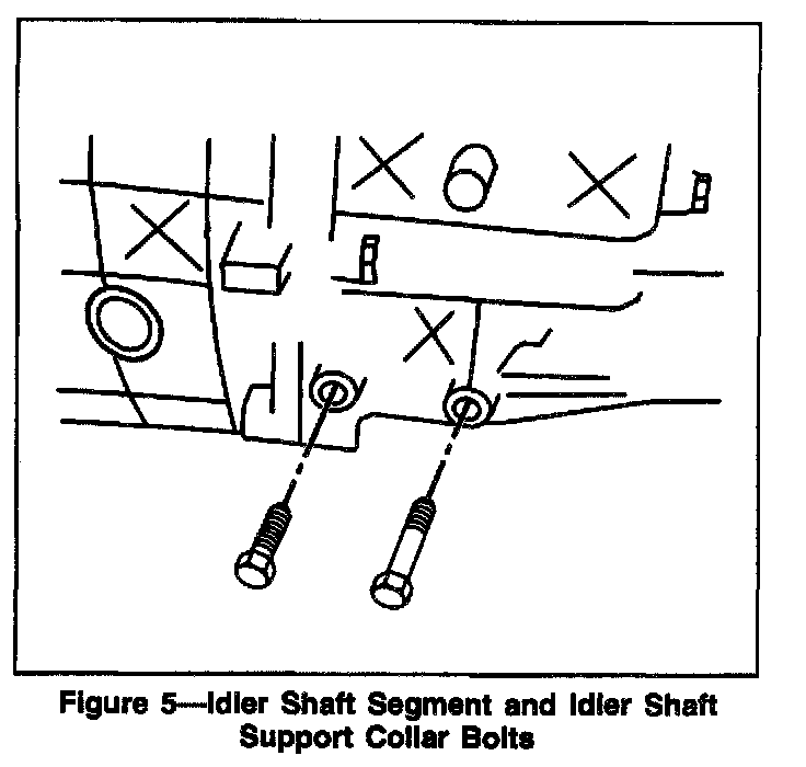
1. Two bolts securing the idler shaft segment and idler shaft support collar to the rear housing.
2. Backup lamp switch from the rear housing.
3. Bolt and electronic speed sensor from the rear housing.
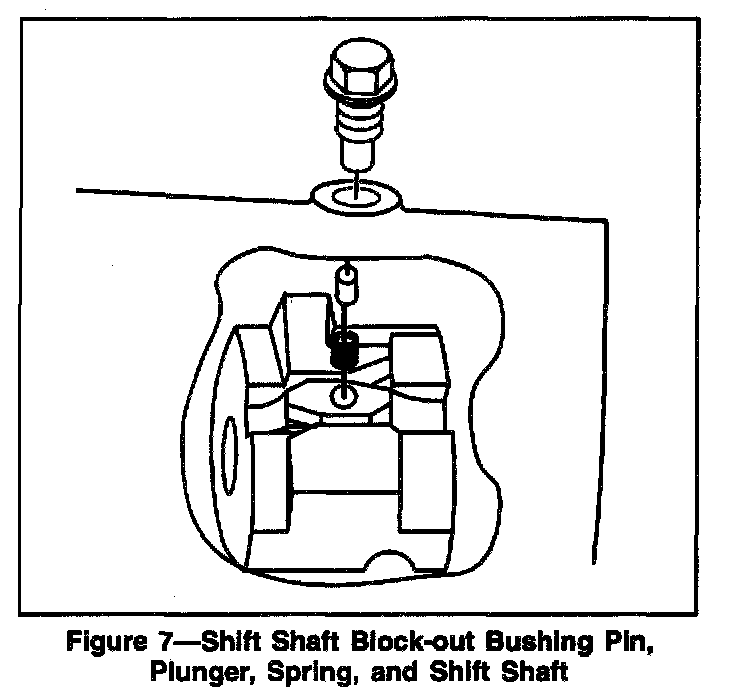
4. Shift shaft block-out bushing pin from the front housing.
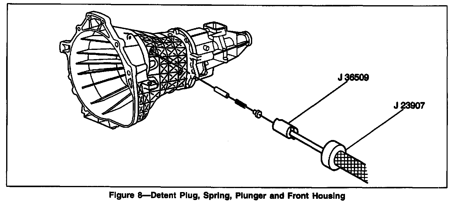
5. Detent plug, spring, and plunger from the front housing using J 36509 and J 23907.
- Slide hammer with 6 mm end into the hole in the front housing.
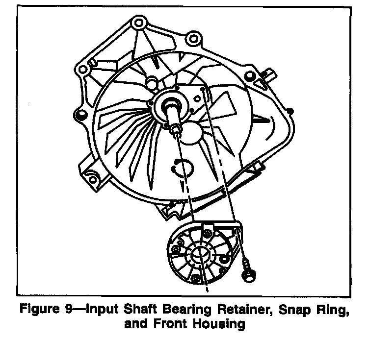
6. Five bolts securing the input shaft bearing retainer to the front housing.
7. Snap ring.
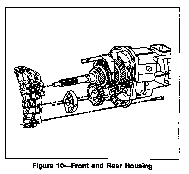
8. Nine bolts securing the front and rear housing to each other.
9. Countershaft roller bearing from the counter shaft or bearing shell.
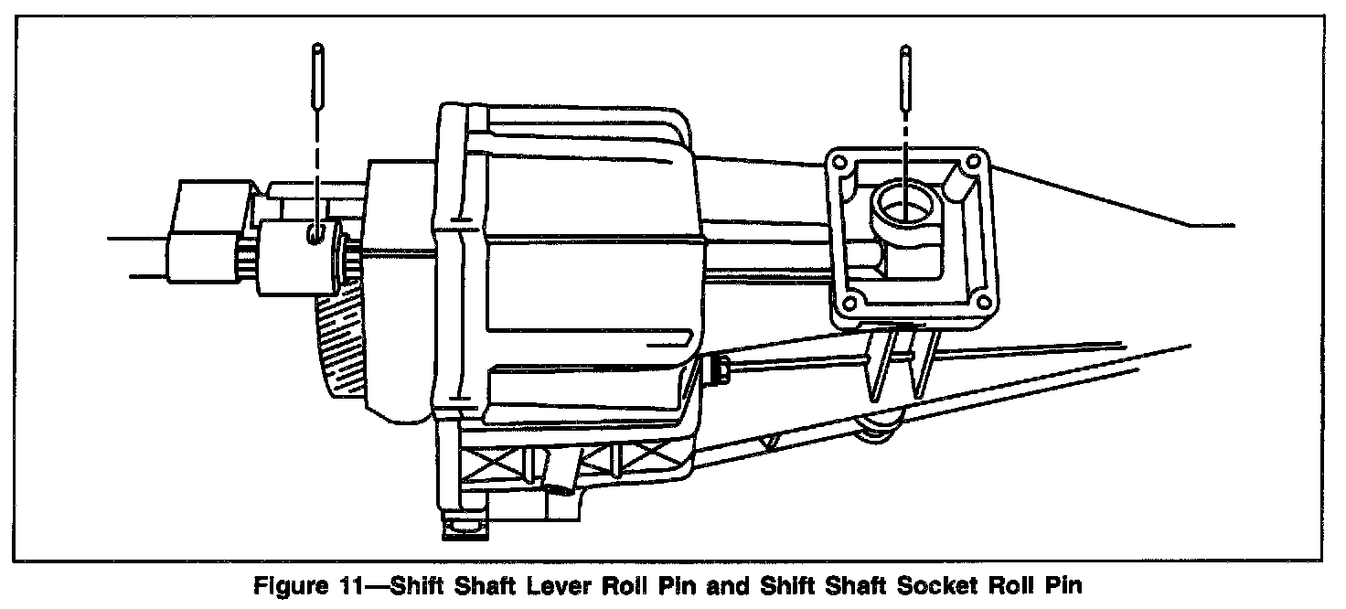
10. Shift shaft lever roll pin from the shift shaft lever.
- Be careful not to lose the shift shaft lever plunger and spring when removing the shift shaft lever roll pin from the rear housing.
Important
A. Rotate the shift shaft lever and shift shaft bushing up.
B. Remove the shift shaft lever plunger and spring.
C. Support the shift shaft end while driving out the shift shaft lever roll pin.
D. Allow the roll pin to clear the second gear during removal.
11. Shift shaft socket roll pin from the bottom of the shift shaft socket.
Important
- Do not bend the shift rail when removing the roll pin.
- Use a air gun with a 5 mm (3/16 inch) drift punch to remove the roll pin.
- The roll pin will fall into the rear housing.
NOTE: Do not use excessive force when removing the shift shaft. Excessive force will "peen" the shift shaft and damage the rear housing shift shaft bearing causing increased shift effort.
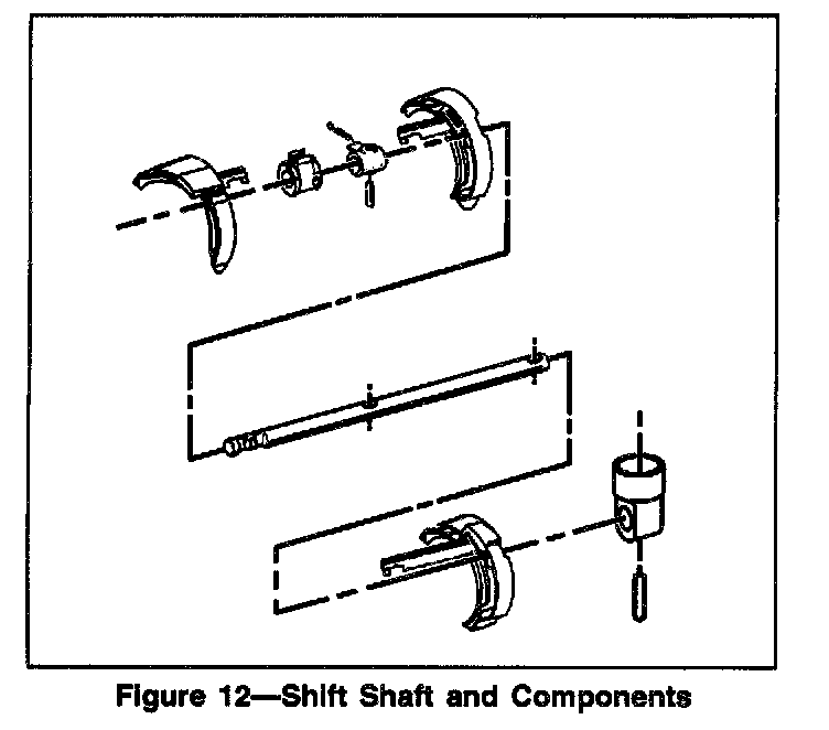
12. Shift shaft, shift shaft socket, lever, and shift shaft block out bushing.
13. Rotate third-fourth shift fork counterclockwise and remove.
14. Five bolts from the center of the rear housing securing the output shaft bearing retainer.
15. Rear housing from the gear assemblies.
16. Reverse idler gear assembly.
17. Output shaft bearing retainer.
18. Shift forks.
19. Countershaft.
20. Countershaft bearing snap ring.
21. Countershaft bearing.
- The countershaft bearing must be pressed off the counter shaft.
22. Fifth counter gear from counter shaft.
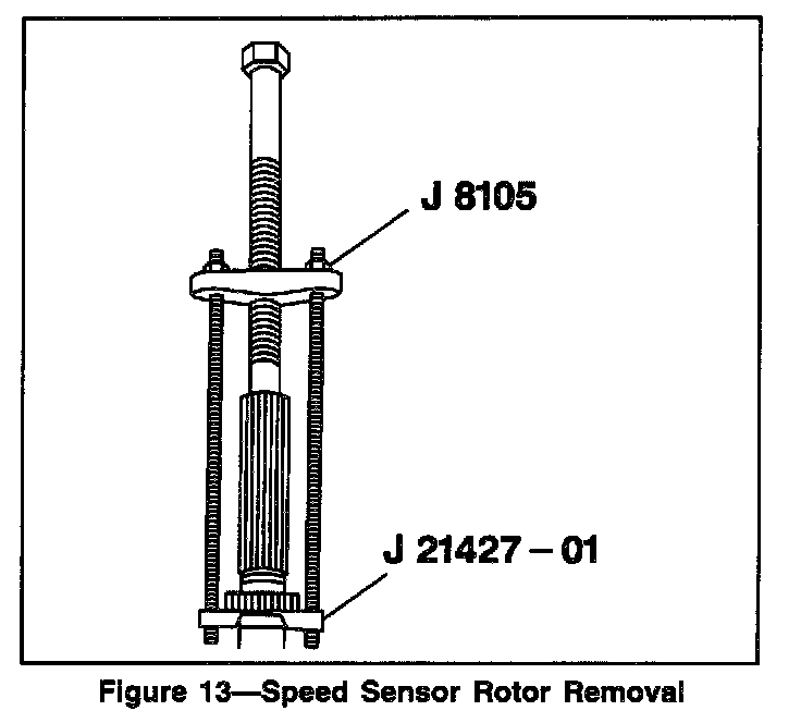
23. Speed sensor rotor from the output shaft using J 21427-01 and J 8105.
- Discard the speed sensor rotor.
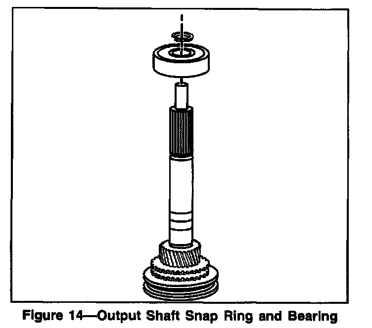
24. Snap ring from the output shaft.
25. Output shaft bearing from the output shaft using J 21427-01 and J 8105.
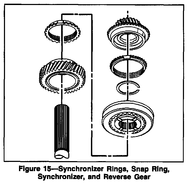
26. Fifth speed gear from the output shaft.
27. Snap ring from the output shaft.
28. Synchronizer blocking ring, Synchronizer and hub, synchronizer blocking ring, and reverse speed gear assembly from the output shaft.
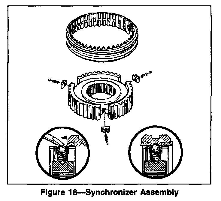
- Leave the synchronizer rings on the fifth-reverse synchronizer assembly to prevent the synchronizer detent balls from popping out.
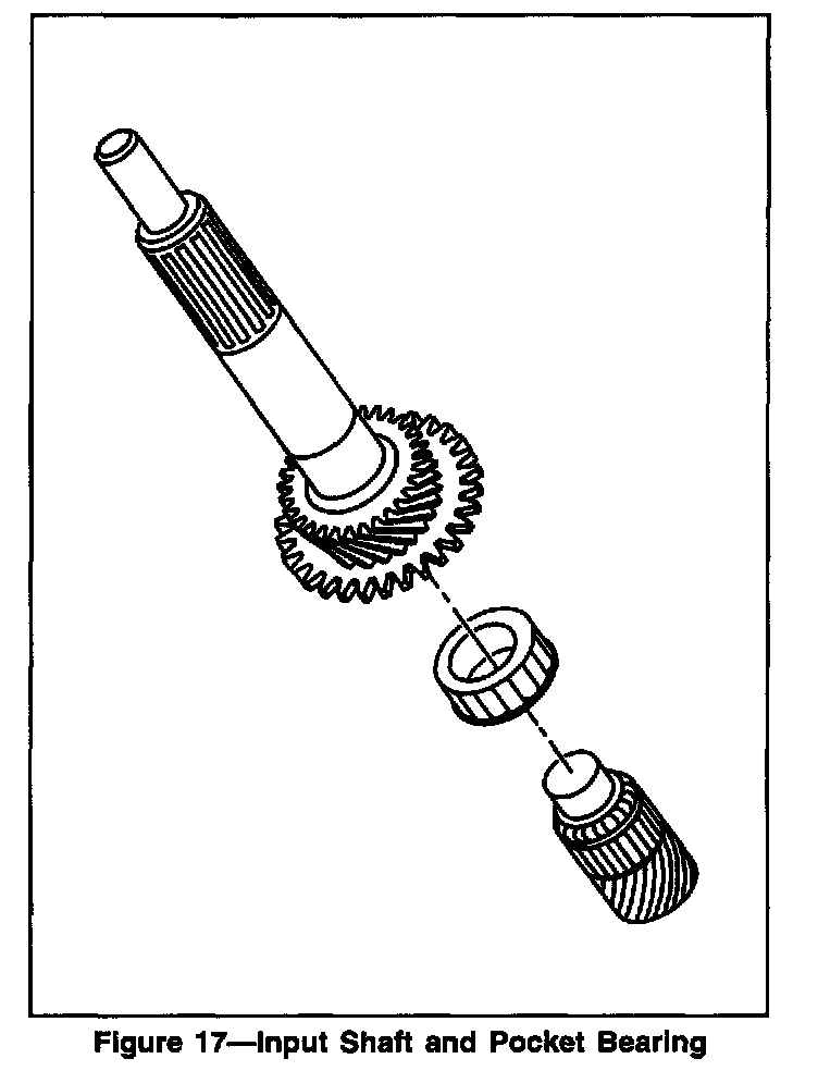
29. Input shaft and pocket bearing from the output shaft.
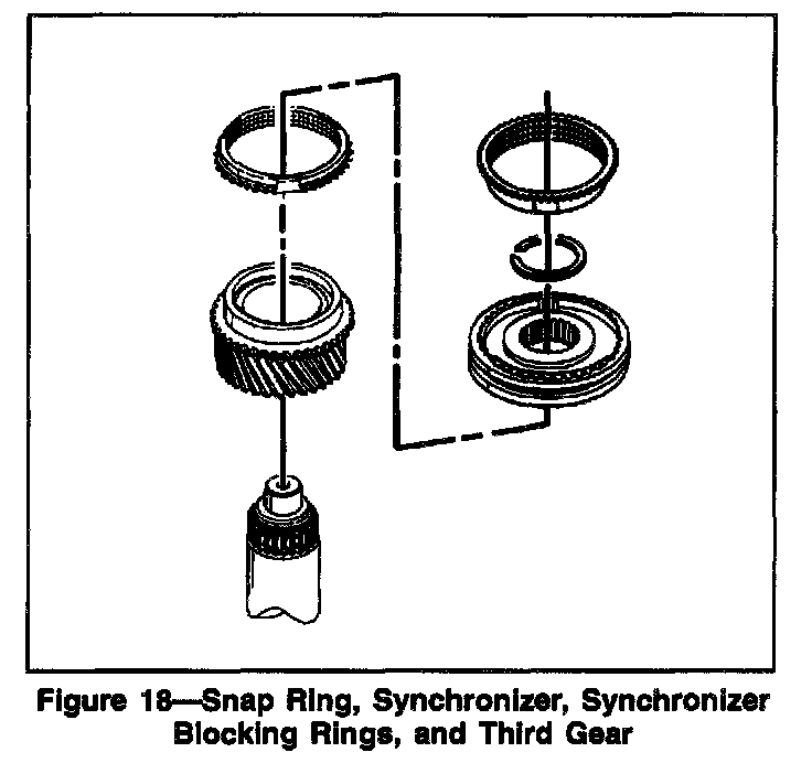
30. Snap ring
31. Third-fourth synchronizer assembly, synchronizer blocking rings, and third speed gear from the main shaft using a hydraulic press
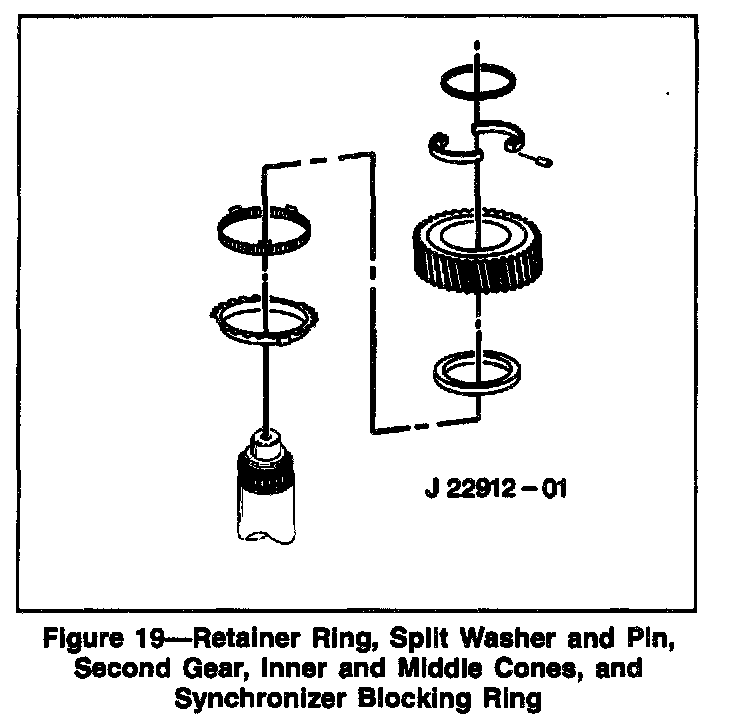
32. Retaining ring, pin, and two thrust washer halves from the main shaft.
33. Second gear from main shaft.
34. Inner. and middle cones and synchronizer ring from the main shaft.
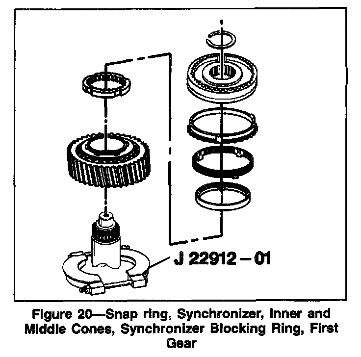
35. Snap ring..
36. Synchronizer, synchronizer ring, inner and middle cones, and first gear from the main shaft using J 22912-01 and hydraulic press.
- Leave the synchronizer rings on the first-second synchronizer assembly to prevent the synchronizer detent balls from popping out.
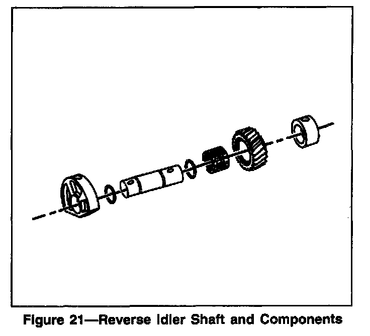
37. Remove the following from the reverse idler shaft:
1. Segment
2. Gear
3. Bearing Assembly
4. Collar
5. Two O-rings from the shaft