Shift Interlock: Testing and Inspection
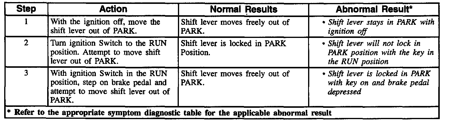
TROUBLESHOOTING HINTS:
- IMPORTANT! Use the appropriate probe from the J 35616-A connector test adapter kit for any probing of the Bussed Electrical Center (BEC's) in this table to avoid damage to the BEC's.
- Perform a visual check of the wiring and connectors.
- Refer to Wiring Systems for intermittent and poor connections.
CIRCUIT OPERATION
When the Brake Transmission Shift Interlock (BTSI) is energized, the solenoid locks the shift lever mechanism in PARK When not energized, the key lock (BTSI) solenoid returns to the unlocked position. Gauges fuse supplies ignition switch RUN or START voltage to the stoplamp switch. Fuse 25 supplies battery voltage to the transmission range switch. Ground is provided at G103 and is permanently connected to the key lock (BTSI) G207 solenoid. With the ignition switch in the RUN or START position, the shift lever in PARK, and the brake pedal released, the solenoid is energized. This locks the shift lever in PARK. Note that the BTSI portion of the stoplamps switch is closed with the brakes released. Depressing the brake pedal opens the switch causing the solenoid to de-energize, unlocking the shift lever. The BTSI portion of the transmission range indicator switch is closed in PARK only. The circuit is not active with the ignition switch off to facilitate towing.