Function and Description
Functional Description
Hydraulic Unit (H/U) Solenoid Valve
System Components
Electronic Hydraulic Control Unit (EHCU), three Wheel Speed Sensors, Warning Light, and G-sensor.
Electronic Hydraulic Control Unit (EHCU)
The EHCU consists of ABS control circuits, fault detector, and a fail-safe. The signal received from each sensor activates the hydraulic unit accordingly and cancels the ABS to return to normal braking if a malfunction occurs in the ABS system. The EHCU has a self-diagnosing function which can indicate faulty circuits during diagnosis. The EHCU is mounted on the engine compartment rear right side. It consists of a Motor, Plunger Pump, Solenoid Valves.
NOTE:
The Electronic Hydraulic Control Unit (EHCU) comprises the Hydraulic Unit (H/U) and the coil Integrated Module.


Normal Braking
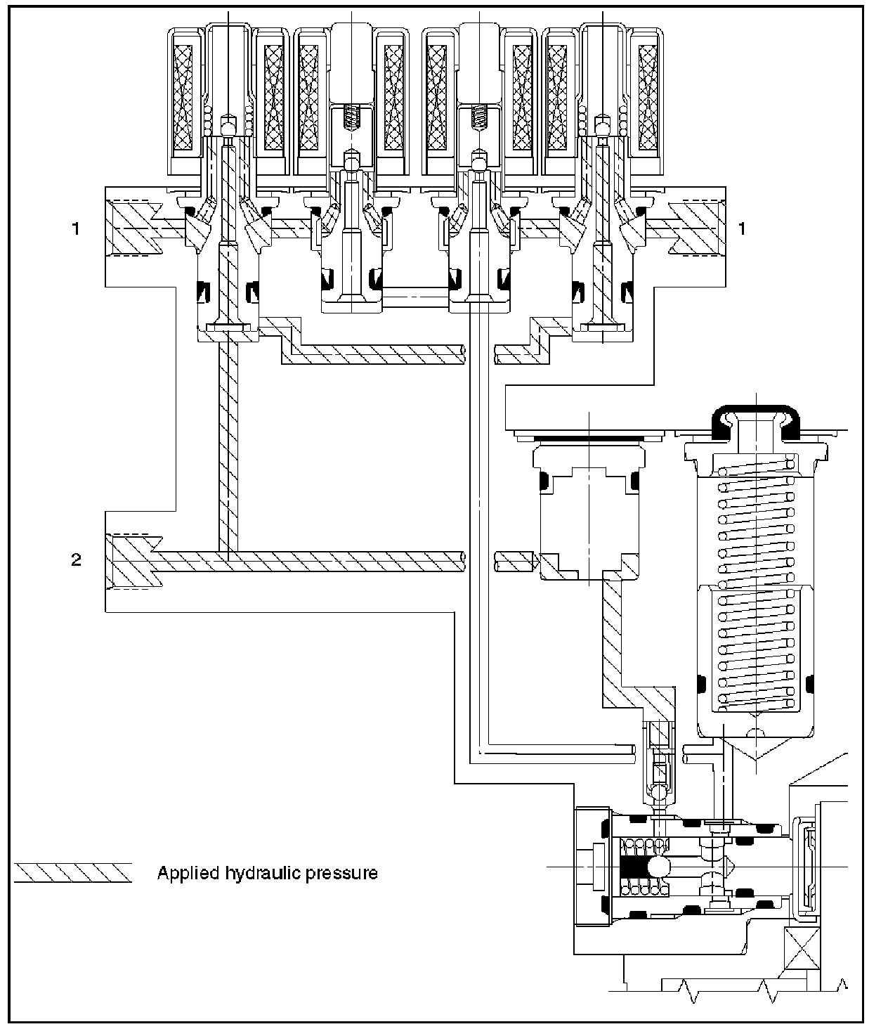
During normal (non anti-lock) braking, the solenoid valves has current flow. The dump valve is closed and the isolation valve is opened due to spring force. Brake fluid travels through the center of the isolation valve (normally open) around the dump valve (normally closed) then to the brake pistons.
Pressure Isolation (Pressure Maintain)
The electro-hydraulic control unit is activated when the brakes are applied. If the information from the wheel speed sensors indicates excessive wheel deceleration (imminent lockup), the first step in the anti-lock sequence is to isolate the brake pressure being applied by the brake pedal. The microprocessor in the coil integrated module sends a voltage to the coil to energize and close the isolation valve. This prevents any additional fluid pressure applied by the brake pedal from reaching the wheel. With the isolation valves closed, unnecessary increase in the brake pressure is prevented.
Pressure Reduction
Once the brake pressure is isolated, it must be reduced to allow the wheels to unlock. This is accomplished by dumping a portion of the brake fluid pressure into a low pressure accumulator. The microprocessor activates the normally closed dump valve to open, allowing fluid from the wheels to be dumped into the accumulator. This is done with very short activation pulses opening and closing the dump valve passageway. Brake pressure is reduced at the wheel and allows the wheel to begin rotating again. The fluid from the brake piston is stored in the accumulator against spring pressure and a portion of this fluid also primes the pump. The dump valves are operated independently to control the deceleration of the wheel.
Pressure Increase (Re-apply)
The re-apply sequence is initiated to achieve optimum braking. The isolation valve is momentarily opened to allow master cylinder and pump pressure to reach the brakes. This controlled pressure rise continues until the wheel is at optimum brake output or until the brake pressure is brought up to the master cylinder output pressure. If more pressure is required, more fluid is drawn from the master cylinder and applied to the brakes. The driver may feel slight pedal pulsations, or pedal drop, this is normal and expected. As fluid is re-applied to the brakes, the wheel speed will reduce. If the wheels approach imminent lockup again, the module will isolate, dump and re-apply again. This cycle occurs in millisecond intervals, allowing several cycles to occur each second. It is a much faster and more controlled way of "pumping the pedal".
Brake Release
At the end of the anti-lock stop, when the brake pedal is released, the pump will remain running for a short time to help drain any fluid from the accumulators. As this fluid returns into the system, the spring forces the piston back to its original position. The isolation valve opens and fluid may return to the master cylinder. Conventional braking is then resumed.
Solenoid Valves
Reduces or holds the caliper fluid pressure for each front disc brake or both rear disc brakes according to the signal sent from the EHCU.
Reservoir
Temporarily holds the brake fluid that returns from the front and rear disc brake caliper so that pressure of front disc brake caliper can be reduced smoothly.
Plunger Pump
Feeds the brake fluid held in the reservoir to the master cylinder.
Motor
Drives the pump according to the signal from EHCU. Check Valve: Controls the brake fluid flow.