Intake Manifold: Service and Repair
Intake ManifoldRemoval
1. Remove the cover and disconnect the battery ground cable.
2. Remove the throttle body.
3. Remove the RH engine cover bracket.
> Remove the 2 nuts.
> Disconnect the electrical connector.
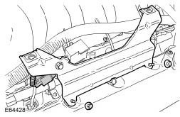
4. Remove the LH engine cover bracket.
> Remove the 2 nuts.
> Release the 2 electrical connectors.
> Remove the purge valve bolt.
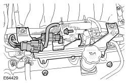
5. Release the engine wiring harness from the intake manifold.
> Release the 4 clips.
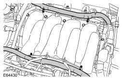
6. Release the wiring harness from the rear of the engine.
> Remove the 2 bolts.
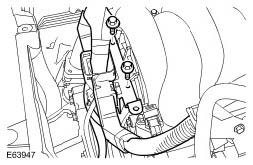
7. Release the RH camshaft position (CMP) sensor electrical connector.
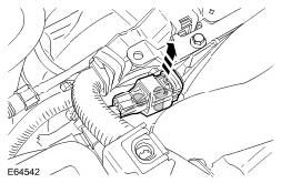
8. Release the purge valve.
> Disconnect the quick release connector.
> Disconnect the electrical connector.
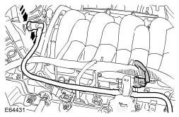
9. Using the special tool, disconnect the fuel line.
10. Disconnect the MAP sensor electrical connector.
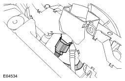
11. Disconnect the fuel rail pressure (FRP) sensor electrical connector.
12. Disconnect the FRP sensor vacuum line.
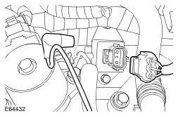
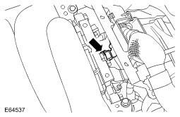
13. Disconnect the knock sensors (KS) electrical connector.
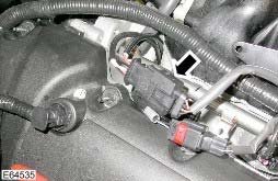
14. Disconnect the 8 fuel injector electrical connectors.
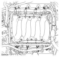
15. Disconnect the fuel temperature sensor electrical connector.
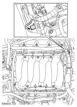
16. Disconnect the throttle body elbow vacuum line.
17. Disconnect the positive crankcase ventilation (PCV) line from the throttle body elbow.
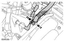
18. Disconnect the brake booster vacuum hose from the intake manifold.
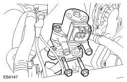
19. Release the exhaust gas recirculation (EGR) valve.
> Remove the 2 bolts.
> Remove and discard the gasket.
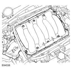
20. CAUTION: Always plug any open connections to prevent contamination.
Remove the intake manifold.
> Remove and discard the 2 gaskets.
> Remove the 10 bolts.
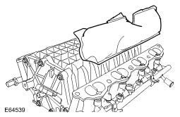
21. NOTE: Do not disassemble further if the component is removed for access only.
Remove the foam pad.
22. Remove the throttle body elbow.
> Remove the 4 bolts.
> Remove and discard the O-ring seal.
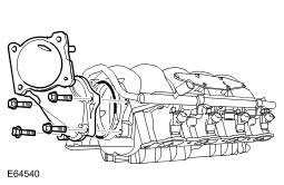
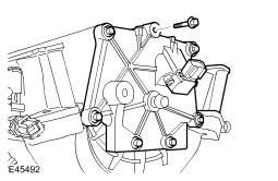
23. Remove the intake manifold MAP sensor housing.
> Remove the 7 bolts.
> Remove and discard the O-ring seal.
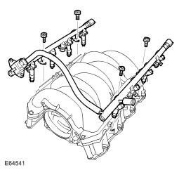
24. Remove the fuel injection supply manifold.
> Remove the 4 Torx bolts.
> Remove and discard the 8 O-ring seals.
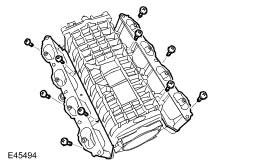
25. Remove the 2 intake manifold housings.
> Remove the 10 Torx screws.
> Remove and discard the 8 O-ring seals.
Installation
1. Install the intake manifold housings.
> Clean the components.
> Install new O-ring seals.
> Tighten the Torx screws to 4 Nm (3 lb.ft).
2. Install the fuel injection supply manifold.
> Clean the components.
> Install new O-ring seals.
> Tighten the Torx bolts to 10 Nm (7 lb.ft).
3. Install the intake manifold MAP sensor housing.
> Clean the components.
> Install a new O-ring seal.
> Tighten the bolts to 10 Nm (7 lb.ft).
4. Install the throttle body elbow.
> Clean the components.
> Install a new O-ring seal.
> Tighten the bolts to 10 Nm (7 lb.ft).
5. Install the foam pad.
6. Install the intake manifold.
> Clean the components.
> Install new gaskets.
> Evenly and progressively tighten the bolts to 20 Nm (15 lb.ft).
7. Attach the EGR valve.
> Clean the components.
> Install a new gasket.
> Tighten the bolts to 10 Nm (7 lb.ft).
8. Connect the brake booster vacuum hose.
9. Connect the PCV line.
10. Connect the throttle body elbow vacuum line.
11. Connect the FRP sensor vacuum line.
12. Connect the fuel temperature sensor electrical connector.
13. Connect the fuel injector electrical connectors.
14. Connect the KS electrical connector.
15. Connect the FRP sensor electrical connector.
16. Connect the MAP sensor electrical connector.
17. Connect the fuel line.
18. Attach the purge valve.
> Connect the electrical connector.
> Connect the quick release connector.
19. Attach the CMP sensor electrical connector.
20. Attach the wiring harness.
> Tighten the bolts to 10 Nm (7 lb.ft).
21. Install the LH engine cover bracket.
> Attach the purge valve, align the peg and tighten the bolt to 6 Nm (4 lb.ft).
> Secure the electrical connectors.
> Tighten the nuts to 6 Nm (4 lb.ft).
22. Install the RH engine cover bracket.
> Connect the electrical connector.
> Tighten the nuts to 6 Nm (4 lb.ft).
23. Install the throttle body.
24. Connect the battery ground cable and install the cover.