Repair Procedure
REPAIR FUEL TRANSFER TUBEWARNING:
Place the vehicle in a quarantined area and arrange "No Smoking/Petrol Fumes" signs about the vehicle.
WARNING:
Before any work is carried out on the fuel system, ground the vehicle to earth and maintain the ground connection until the work is complete.
WARNING:
Do not smoke or carry lighted tobacco or open flame of any type when working on or near any fuel related components. Highly flammable vapors are always present and may ignite. Failure to follow these instructions may result in personal injury.
WARNING:
The fuel system remains pressurized for a long time after the ignition is switched off. The fuel pressure must be relieved before attempting any repairs. Failure to follow these instructions may result in personal injury.
WARNING:
After carrying out repairs, the fuel system must be checked visually for leaks. Failure to follow these instructions may result in personal injury.
WARNING:
This procedure involves fuel handling. Be prepared for fuel spillage at all times and always observe fuel handling precautions. Failure to follow these instructions may result in personal injury.
WARNING:
If taken internally, do not induce vomiting, seek immediate medical attention. Failure to follow these instructions may result in personal injury.
WARNING:
If fuel contacts the eyes, flush the eyes with cold water or eyewash solution; seek immediate medical attention.
CAUTION:
Ensure vehicle has less than three-quarters (3/4) of a tank of fuel before beginning Repair Procedure.
1. Ensure fuel level is less than three-quarters (3/4) of a tank.
NOTE:
Global Technical Reference (GTR) lookup sequence is as follows:
GTR Home > NAS > X250 - XF > Service Information > 2010 > Workshop Manual
2. Refer to Workshop Manual (GTR) section 310-00 and depressurize the fuel system.
3. Refer to Workshop Manual (GTR) section 414-01 and disconnect the negative battery cable.
4. Refer to Workshop Manual (GTR) section 501-10 and remove the rear seat cushion.
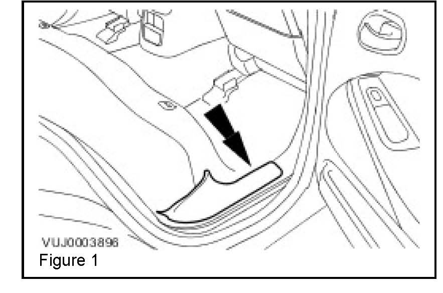
5. Remove the right-rear door scuff plate trim panel. (Figure 1)
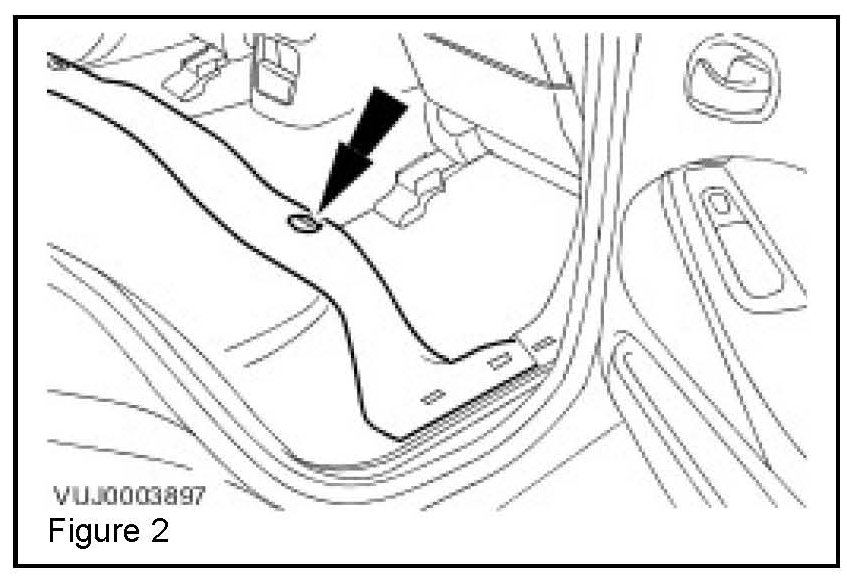
6. Detach and reposition the floor covering. (Figure 2)
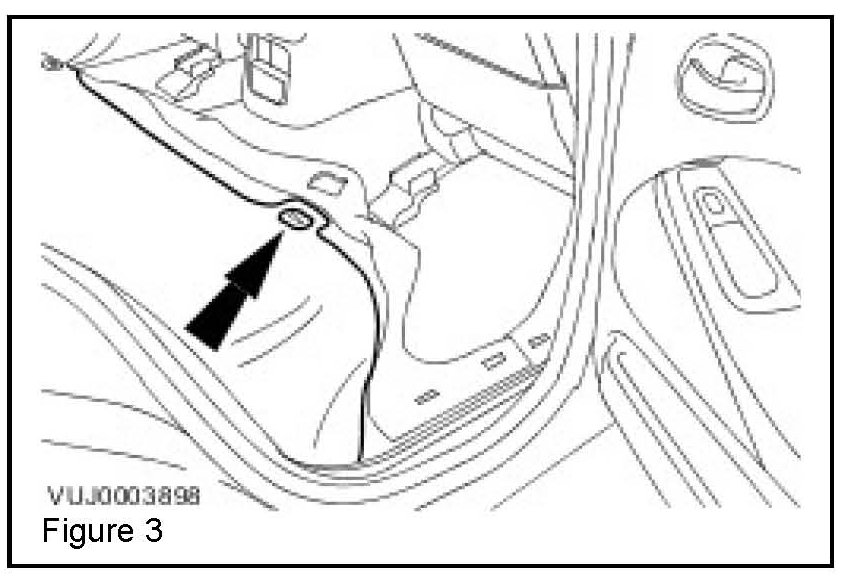
7. Detach and reposition the rear seat cushion insulation. (Figure 3)
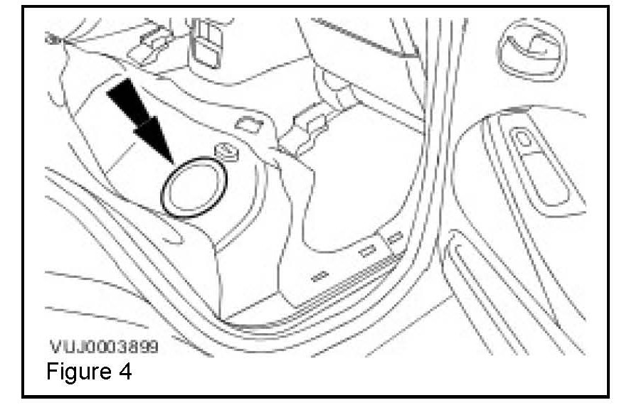
8. Remove the floor aperture cover. (Figure 4)
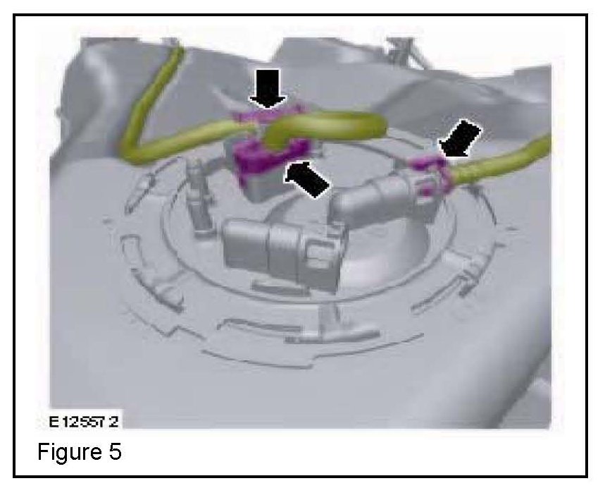
9. Disconnect the fuel pump module electrical connector. (Figure 5)
10. Detach the fuel pump module wiring harness from the retaining bracket. (Figure 5)
11. Disconnect the fuel pump module quick release coupling. (Figure 5)
WARNING:
Do not work on or under a vehicle supported only by a jack. Always support the vehicle on safety stands.
12. Raise and support the right-hand (RH) side of the vehicle to enable the transfer of fuel to the left-hand (LH) side of the tank; this will expose the fuel transfer pipe connection in the module.
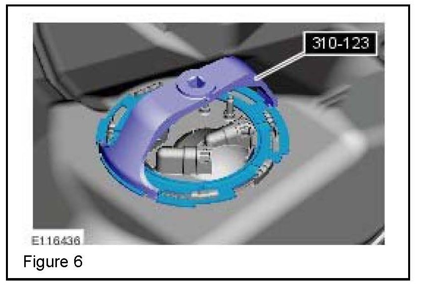
13. Using special tool 310-123, remove the fuel pump module locking ring. (Figure 6)
14. Remove and discard flange O-ring seal.
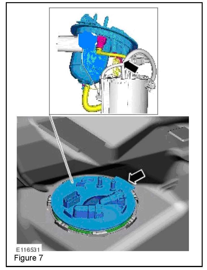
15. Disconnect the fuel transfer module transfer feed tube. (Figure 7)
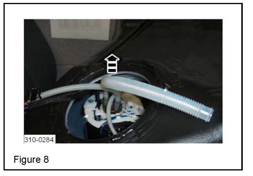
16. Reposition the fuel transfer module transfer feed tube; cut away and discard 150mm (6 in) from the disconnected end of the tube. (Figure 8).
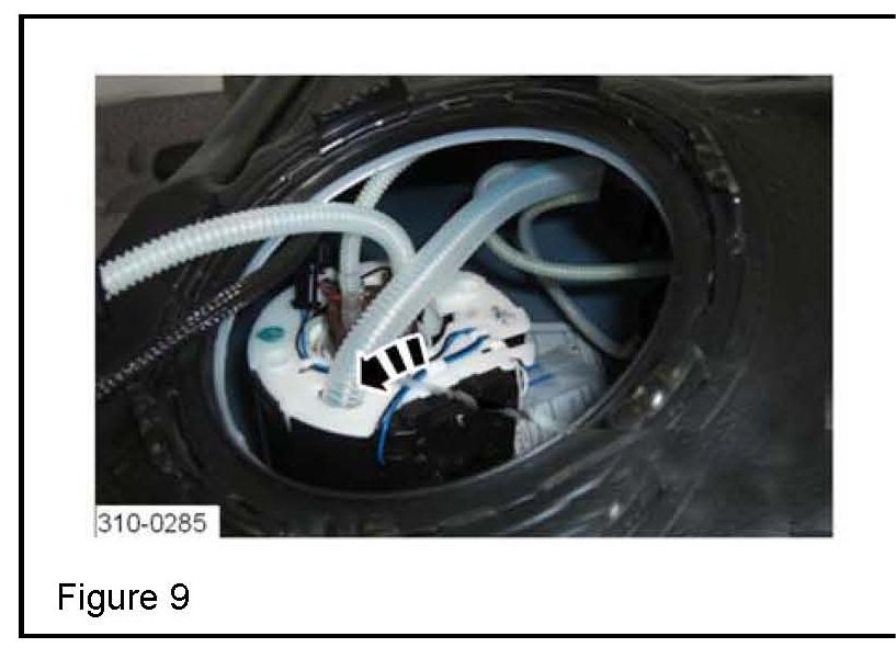
17. Insert the fuel transfer module transfer feed tube into the triangular-shaped hole in the swirl pot. (Figure 9)
CAUTION:
Ensure the arrow on the fuel transfer module and the 'NA' marker on the fuel tank are aligned.
18. Secure the fuel pump module:
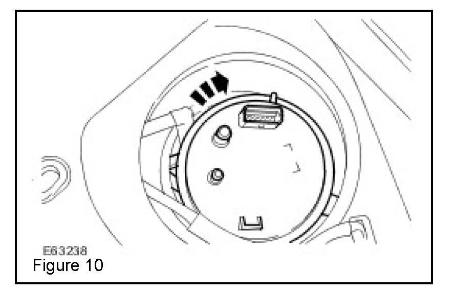
^ Press down and rotate the base of the fuel pump module clockwise. (Figure 10)
19. Install new flange O-ring seal (C2Z 7361).
*CAUTION:
When tightening the fuel pump module lock ring, an audible 'click' may be heard when the lock ring is fully seated in its stop.*
20. *Use special tool 310-123 to install the fuel pump module lock ring:
^ An audible 'click' may be heard when the lock ring is fully seated in its stop. The torque necessary to fully seat the lock ring may be as high as 250 Nm (185 lbf ft).*
21. Lower vehicle.
22. Connect the fuel pump module quick release coupling:
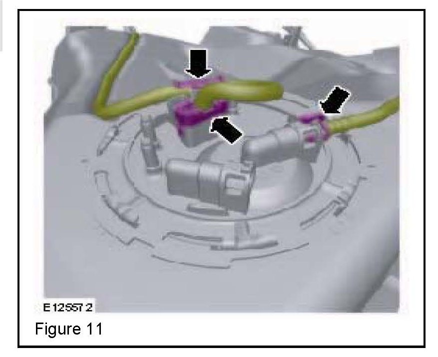
^ Ensure the quick release coupling has latched onto the fuel pump module by pulling the tube after the connection has been made. (Figure 11)
23. Attach the fuel pump module wiring harness to the retaining
bracket. (Figure 11)
24. Connect the fuel pump module electrical connector. (Figure 11)
25. Install the floor aperture cover.
26. Attach the rear seat cushion insulation.
27. Attach the floor covering.
28. Install the right-rear door scuff plate trim panel.
29. Refer to Workshop Manual (GTR) section 501-10 and install the rear seat cushion.
30. Refer to Workshop Manual (GTR) section 414-01 and connect the negative battery cable.
31. Ensure no fuel leakage.
32. Connect the Midtronics PSC-550 Vehicle Power Supply to the vehicle battery, connect the IDS to the vehicle, and clear Diagnostic Trouble Codes (DTC).