Driver Side Register
Driver Side Register
This is a "Trustmark Authoring Standards (TAS) Repair Procedure"
- TAS style procedures can be identified by steps that have no accompanying step text and the magenta color of the electrical connectors and fasteners such as nuts, bolts, clamps or clips.
- TAS removal and installation procedures use a sequence of color illustrations to indicate the order to be followed when removing/disassembling or installing/assembling a component.
- Many of the TAS procedures will have the installation information within the removal steps.
- The TAS color illustrations use a variety of symbols to indicate important details of the procedures. It is important to understand these symbols in order to properly used the TAS procedures.
Refer to How to Use TAS Procedures and TAS Symbol Glossary at Vehicle | Description and Operation for additional information on these TAS procedures.
For additional information, refer to How to Use TAS Procedures How to Use TAS Procedures
For additional information, refer to TAS Symbol Glossary TAS Symbols Glossary
Removal
NOTE:
Removal steps in this procedure may contain installation details.
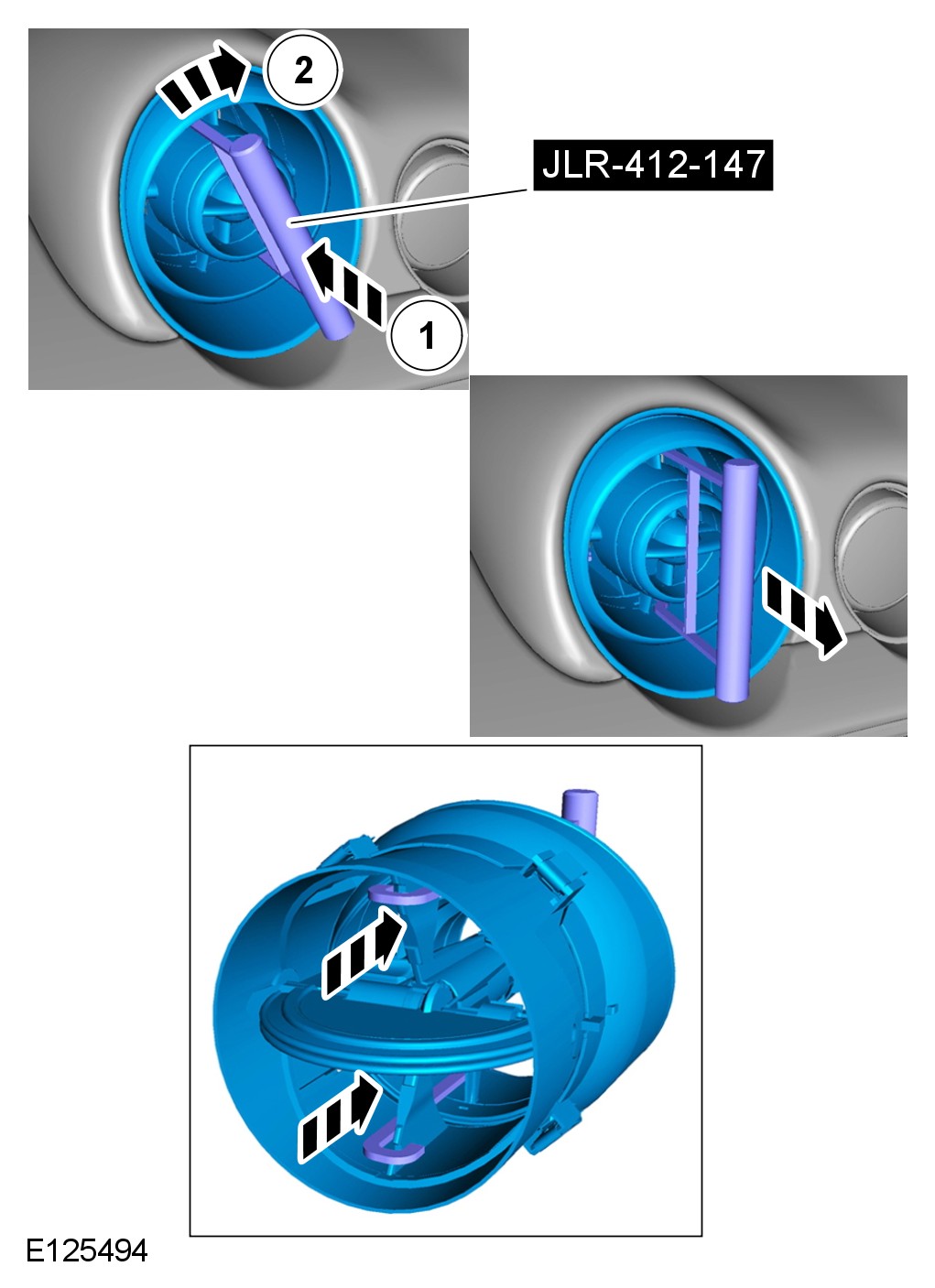
CAUTION: Before inserting the special tool, make sure that the register is fully open.
CAUTION: Care must be taken to avoid damage to the internal components of the center registers.
CAUTION: To install the register, align the securing clips and push the register into the housing until firmly secured in it's seated position.
CAUTION: During removal, care must be taken not to damage the instrument panel covering with the register clips.
NOTE:
Some variation in the illustrations may occur, but the essential information is always correct.
Special Service Tool
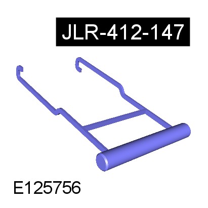
Remover, Register, JLR-412-147
Installation
1 To install, reverse the removal procedure.