Procedure
Testing1. Connect the MS 1700 diagnostic tester to the vehicle diagnostic connectors.
2. Place the MS 1700 in the State Display mode and select the Sync Pulse Status Display.
3. If the vehicle will start, start the engine.
If the vehicle will not start, crank the engine while performing the next step.
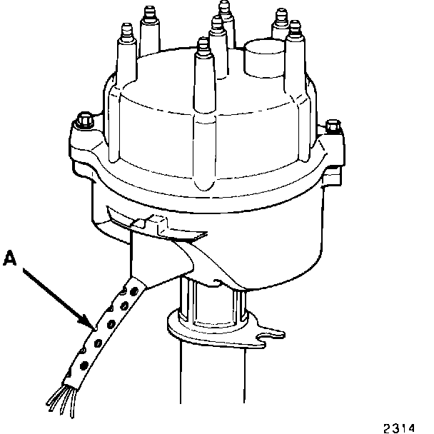
4. With the engine running or cranking, flex the distributor stator lead (A) while viewing the tester display.
If "No Sync Signal" is displayed or the display indicator arms stop or intermittently stop moving, perform Stator Harness Replacement.
If no problem is found with the sync signal, select the TPS Status display on the MS 1700 tester and continue with step 5.
5. With the engine at idle or the key in the ON position, observe the tester display. In the idle position, with the throttle closed, a "C" should be displayed. If anything else is displayed or the "C" intermittently changes to another reading, perform Throttle Position Sensor (TPS) Replacement.
6. Turn the key to the OFF position.
Stator Harness Replacement
1. Disconnect the battery negative cable.
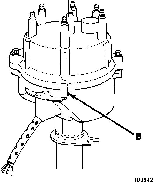
2. Scribe a mark (B) on the distributor housing directly below the number one spark plug wire post of the distributor cap to use as a reference for #1 firing position.
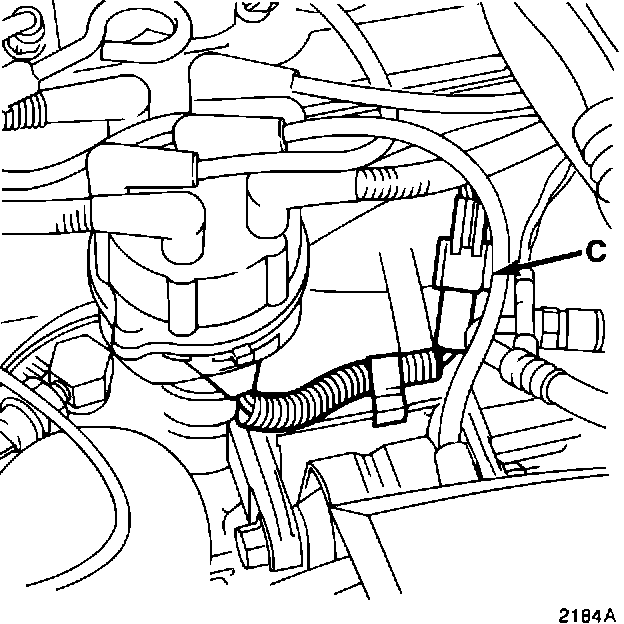
3. Disconnect the distributor electrical connector (C).
4. Remove the distributor cap.
5. On vehicles equipped with an electric cooling fan, remove it and the shroud assembly from the radiator. This will provide room to turn the engine with a socket and ratchet using the vibration damper bolt.
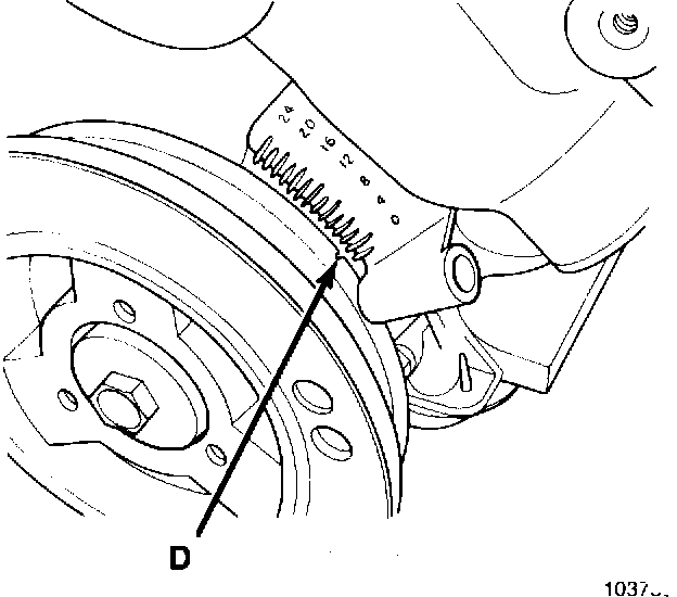
6. Turn the engine in a clockwise direction until the rotor is approaching the scribed mark on the distributor housing. Then slowly turn the engine until the timing mark on the crankshaft vibration damper (D) lines up with zero (0) on the front cover timing scale.
7. Align the trailing edge of the rotor blade with the mark (B) scribed on the distributor housing.
8. Remove the distributor hold down clamp bolt.
9. Remove the distributor.
10. Remove the distributor rotor.
CAUTION: DO NOT position the distributor in a vise. The housing will be deformed. Use wooden V-blocks to support the distributor.
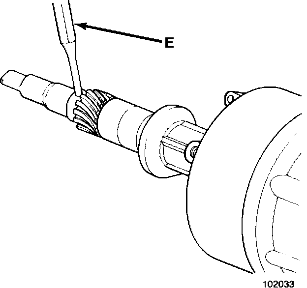
11. Using a small punch (E) and a hammer, remove the distributor drive gear roll pin.
12. Using a brass hammer or rubber mallet, lightly tap the bottom end of the distributor shaft until the drive gear is removed.
13. Remove the distributor shaft from the distributor housing.
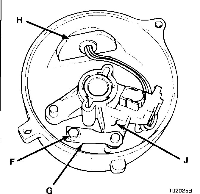
14. Remove stator retaining screw (F) and stator positioning arm (G).
15. Remove the stator harness by pushing the grommet (H) into the housing. Remove stator assembly (J).
NOTE: When installing the stator, DO NOT use the wire harness to pull the grommet through the hole. This can break wires in the harness.
16. Pass the connector of the stator harness through the opening in the distributor housing. Using only finger pressure press the rubber grommet in place.
17. Position the new stator assembly (J) into the distributor.
18. Install stator retaining screw (F) and stator positioning arm (G).
19. Install the distributor shaft into the distributor housing.
CAUTION: DO NOT position the distributor in a vise. The housing will be deformed. Use wooden V-blocks to support the distributor.
20. Using a small punch and a hammer, install the distributor drive gear roll pin.
21. Install the distributor rotor.
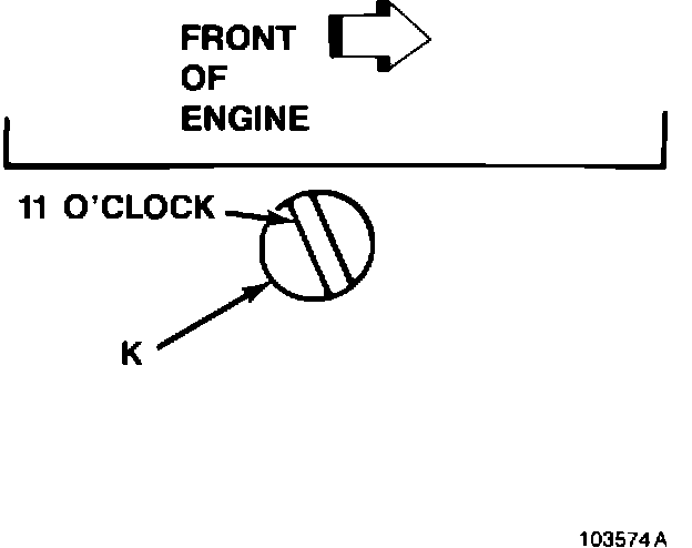
22. If necessary, using a flat blade screwdriver, turn the oil pump gear shaft (K) until the slot is slightly past the 11 o'clock position.
NOTE: The oil pump gear shaft is located do in the distributor hole.
23. Without engaging the distributor gear into the cam gear, position the distributor into the hole in the engine block. Be sure the distributor gasket is installed.
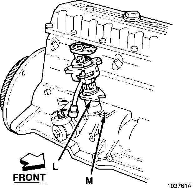
24. Visually line up the hold down ear (L) of the distributor housing with the hold down clamp hole (M).
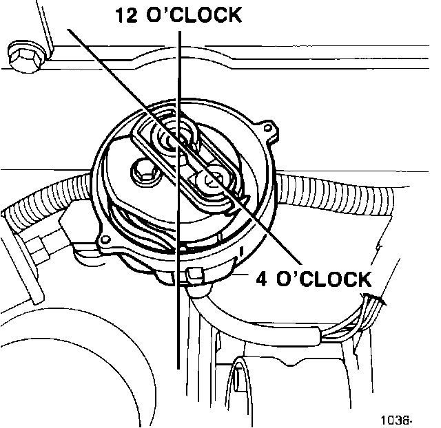
25. Turn the rotor to the 4 o'clock position.
26. Slide the distributor down into the block until it seats. Keep the hold down ear aligned to the hole in the block.
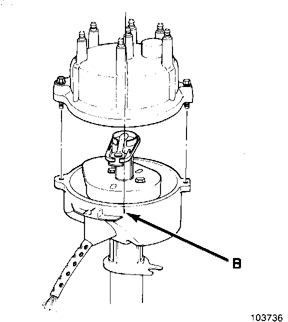
27. The rotor should be in the 5 o'clock position with the trailing edge of the rotor blade lined up with the mark (B) previously scribed on the distributor housing (number one spark plug wire post location).
28. Install the distributor hold down clamp bolt and tighten to 13-19 N-m (9.5-14 ft.lbs).
29. Install the distributor cap and connect the distributor electrical connector.
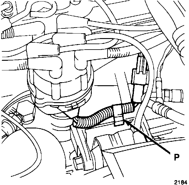
30. Install a new harness clip (P), PN 8953 005 253, to hold the stator harness to the engine block as shown.
31. Install electrical cooling fan and shroud if applicable.