Front Wiper Switch Continuity Test
Fig. 2 Wiper Switch Continuity Chart. Dash Mounted Wiper Switch:
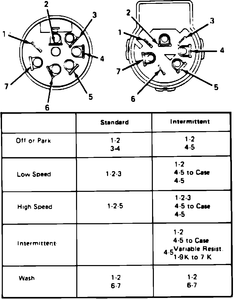
1. For dash mounted wiper switch, proceed as follows:
a. Check switch continuity using a test lamp or ohmmeter. Continuity should exist at various switch positions between terminals shown.
b. On intermittent wiper systems, measure variable resistance between terminals 4 and 5, if intermittent wipe cycle does not operate. Resistance should measure 5600-8400 ohms with control knob rotated to full counterclockwise position and decrease to 100-900 ohms as knob is rotated clockwise.
c. If switch does not meet continuity and resistance specifications, it must be replaced. If switch performs satisfactorily, check wiring for proper continuity.
Fig. 3 Wiper Switch Continuity Chart. Column Mounted Wiper Switch w/standard Wiper:
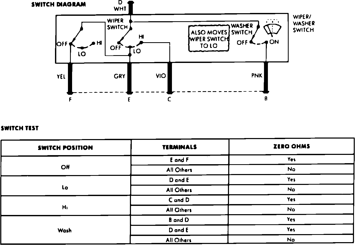
Fig. 4 Wiper Switch Continuity Chart. Column Mounted Wiper Switch w/intermittent Wiper:
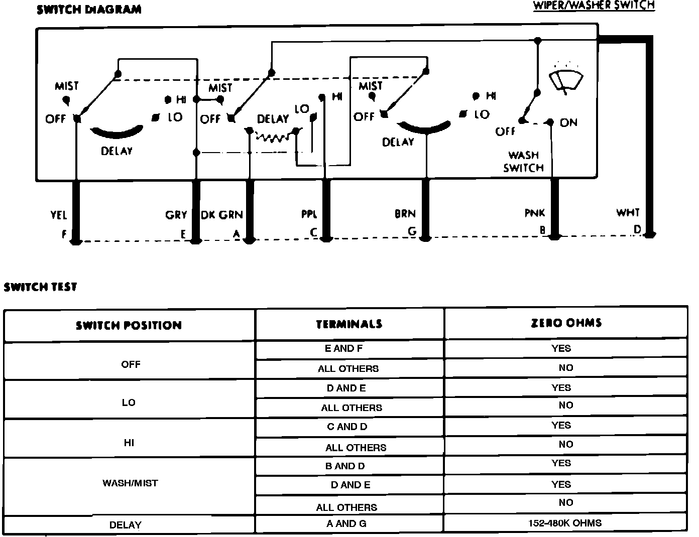
2. For column mounted wiper switch, proceed as follows:
a. Check switch continuity using a ohmmeter. Continuity should exist at various switch positions between terminals shown. If switch does not meet continuity and resistance specifications, it must be replaced. If switch performs satisfactorily, check wiring for proper continuity.