Exhaust Manifold/Oxygen Sensor - Installation
C. INSTALL EXHAUST MANIFOLD AND OXYGEN SENSOR:1. Install the oxygen sensor from the emissions service package into the new exhaust manifold. Tighten to 22 ft-lbs (30 Nm).
2. Transfer the EGR tube to the new manifold using the supplied bolts and gasket. Tighten the bolts to 14 ft-lbs (19 Nm).
3. If the exhaust manifold studs are broken, replace them with the studs supplied in the manifold package.
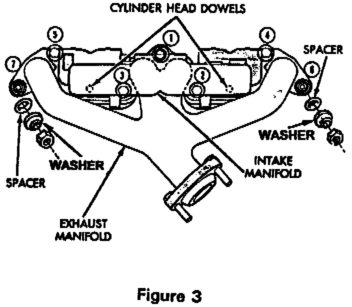
4. Install the supplied spacers on the exhaust manifold studs # 6 and # 7 (Figure 3).
5. Install the exhaust manifold on the studs. The exhaust manifold must be centrally located over the studs and spacers. Loosely install the provided bolt # 1 and nuts with washers for studs # 6 and # 7 (Figure 3).
6. Clean the old intake manifold gasket material from the intake manifold and cylinder head. Then install the provided intake manifold gasket over the alignment dowels on the cylinder head.
7. Install the intake manifold and loosely install the provided bolts and washers for bolt locations # 2, # 3, # 4 and # 5 (Figure 3).
8. Tighten bolt # 1 to 30 ft-lbs (41 Nm).
9. Tighten bolts in the following torque sequence; # 2, # 3, # 4 and then # 5 to 23 ft-lbs (31 Nm).
10. Tighten nuts # 6 and # 7 to 23 ft-lbs (31 Nm).
11. Tighten the EGR tube intake manifold nut to 30 ft-lbs (41 Nm).
12. Connect the four vacuum hoses to the throttle body (Figure 1).
13. Connect all vacuum hoses (MAP sensor, EGR, air cleaner, brake booster) to the vacuum tube assembly (Figure 1)
14. Install the CCV hose at the rear of the cylinder head cover.
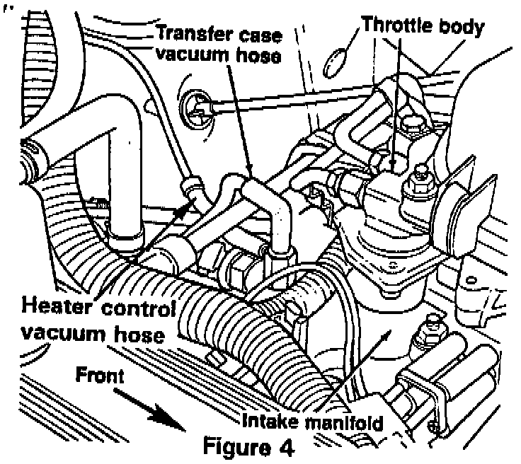
15. Connect the heater control vacuum hose to the vacuum port on the intake manifold (Figure 4).
16. Replace the transfer case vacuum hose (if equipped) with the hose provided in the emission service package. Attach the hose to the metal transfer case vacuum tube and the vacuum port on the intake manifold (Figure 4).
17. Install the two bolts which secure the vacuum tube assembly to the intake manifold.
18. Install the AIS motor and bracket on the throttle body.
19. Connect the accelerator cable and speed control cable to the holddown bracket and throttle arm.
20. Connect the fuel return and fuel supply lines to the throttle body.
21. Attach the heater hoses to the intake manifold.
22. Connect the TPS, AIS, thermostat and intake manifold coolant temperature sensors, fuel injector, air temperature sensor and oxygen sensor electrical connectors (Figure 1).
23. Install the power steering pump and bracket assembly to the water pump and intake manifold.
24. Tighten the accessory drive belt to the proper tension.
25. Install the heated air hose.
26. Connect the air in let bonnet and hose to the throttle body and air cleaner.
27. For Wrangler (YJ) vehicles only:
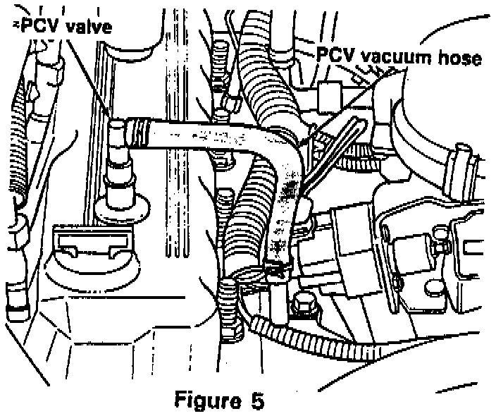
a. Locate the PCV vacuum hose (Figure 5).
b. Remove old PCV hose from vacuum tubing and PCV valve.
c. Install provided PCV vacuum hose from emission service package.
28. Raise vehicle on hoist.
29. Connect exhaust downpipe to exhaust manifold. Tighten the provided nuts to 23 ft-lbs (31 Nm).
30. For Wrangler (YJ) models equipped with a 15 gallon steel fuel tank only:
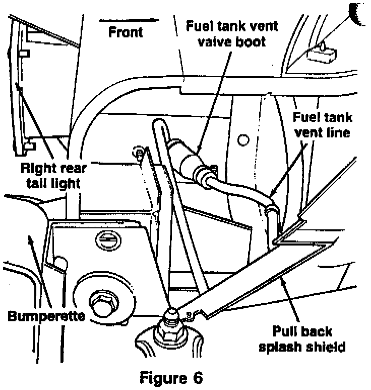
a. Pull back splash shield and locate fuel tank vent valve in fuel vent line in right rear fender well of vehicle (Figure 6).
b. Disconnect clamp at small end of boot and pull boot from vent line.
c. Using a sharp utility knife, slice side of rubber boot and remove it from the vent valve. Be careful not to cut the vent valve.
d. Install provided boot on vent valve.
Note:
A few drops of automatic transmission fluid (ATF) may be used to aid boot installation.
e. Install small end of boot on fuel vent line and install clamp.
f. Reinstall splash shield.
31. Lower vehicle.
32. Connect the negative battery cable.
33. Refill the cooling system.
34. Continue with Step H in the "Emissions Components - Removal/Installation" section.