Ignition Switch: Service and Repair
REMOVAL
1. Disconnect negative battery cable.
2. Tilt column: Remove tilt lever (counter-clockwise)
3. Remove upper and lower covers (three screws).

4. Remove ignition switch mounting screws (Snap-on torx bit tool No. TTXR20B0 or equivalent required).
5. Gently pull switch away from column. release two connector locks on the 7 terminal wiring connector. Remove the connector from the igntion switch.

6. Release connector lock on Key-In-Switch and Halo Light 4-terminal connector. Remove the connector from the ignition switch.
7. Remove the key cylinder from ignition switch as follows:

(a) With the key inserted and the ignition switch in the lock position, proceed as follows: Use a small screwdriver to depress the key cylinder retaining pin flush with key cylinder surface.
(b) Rotate the key clockwise to OFF position. The key cylinder should now be unseated from the ignition switch assembly.
CAUTION: Do not remove the key cylinder at this time.

(c) With the key in cylinder in the unseated position (key bezel about 1/8 inch above ignition switch halo light ring), proceed as follows: Rotate the key counterclockwise to the lock position and remove the key.
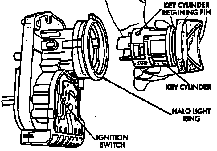
(d) Remove the key cylinder.
INSTALLATION
1. Install electrical connectors to switch. Make sure that the switch locking tabs are fully seated in the wiring connectors.

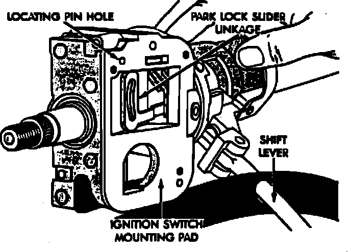
2. Mount ignition switch to column. Park-lock dowel pin on ignition switch assembly must engage with column park-lock slider linkage. Verify ignition switch is in lock position (flag is parallel with the ignition switch terminals) Apply a dab of grease to flag and pin. Position park-lock link and slider to mid-travel. Position ignition switch against lock housing face. Be sure pin is inserted into park-lock link contour slot. Tighten retaining screws to 2 N-m (17 inch lbs.).
3. Assemble cover to the column ( 3 screws). Tighten retaining screws to 2 N-m (17 inch lbs.)
4. Tilt column: Install tilt lever (clockwise).
5. Install negative battery cable.
6. Install key cylinder.
(a) With the key cylinder and ignition in the lock position, gently insert key cylinder into ignition switch assembly until it bottoms.
(b) Insert key. While gently pushing on the key cylinder (inward) toward the ignition switch, rotate key clockwise to end of travel.
7. Check for proper operation of push-to-lock, halo lighting Accessory, Lock, Off, Run, Start, column lock and shift lock (if applicable).