Heater-A/C System
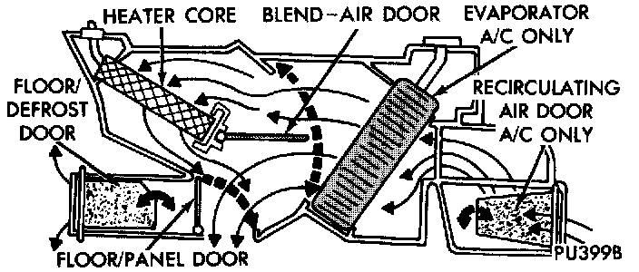
Fig 1 Common Blend-Air Heater-Air Conditioner System -- Typical:
HEATER AND AIR CONDITIONER
All vehicles are equipped with a common heater-A/C housing assembly. The system combines air conditioning, heating, and ventilating capabilities in a single unit housing mounted under the instrument panel. On heater-only systems, the evaporator coil and recirculating air door are omitted from the housing.
Outside fresh air enters the vehicle through the cowl top opening at the base of the windshield, and passes through a plenum chamber to the heater-A/C system blower housing. Air flow velocity can then be adjusted with the blower motor speed selector switch on the heater-A/C control panel. The air intake openings must be kept free of snow, ice, leaves, and other obstructions for the heater-A/C system to receive a sufficient volume of outside air.
The heater and optional air conditioner are blend-air type systems. In a blend-air system, a blend-air door controls the amount of unconditioned air (or cooled air from the evaporator on models with air conditioning) is allowed to flow through, or around, the heater core. A temperature control lever on the heater-A/C control panel determines the discharge air temperature by moving a cable, which operates the blend-air door. This allows an almost immediate manual control of the output air temperature of the system.
The mode control lever on the heater-A/C control panel is used to direct the conditioned air to the selected system outlets. Both mode control switches use engine vacuum to control the mode doors through vacuum actuator motors.
On air conditioned vehicles, the outside air intake can be shut off by selecting the Recirculation Mode with the mode control knob. This will open a vacuum actuated recirculating air door and recirculate the air that is already inside the vehicle.
The optional air conditioner for all models is designed for the use of non-CFC, R-134a refrigerant. The air conditioning system has an evaporator to cool and dehumidify the incoming air prior to blending it with the heated air. This system uses a fixed orifice tube in the liquid line near the condenser outlet tube to meter refrigerant flow to the evaporator coil. To maintain minimum evaporator temperature, a fixed pressure setting switch on the accumulator cycles the compressor clutch.
HEATER AND AIR CONDITIONER CONTROL
Both the heater-only and heater-A/C systems use a combination of mechanical, electrical, and vacuum controls. These controls provide the vehicle operator with a number of setting options to help control the climate and comfort within the vehicle. Refer to the owners manual for more information on the suggested operation and use of these controls.
The heater-only or heater-A/C control panel is located in instrument panel center bezel below the radio and above the accessory switch bezel and ash receiver. The control panel contains a sliding-type temperature control knob, a sliding-type mode control switch knob, and a rotating-type blower motor speed switch knob.
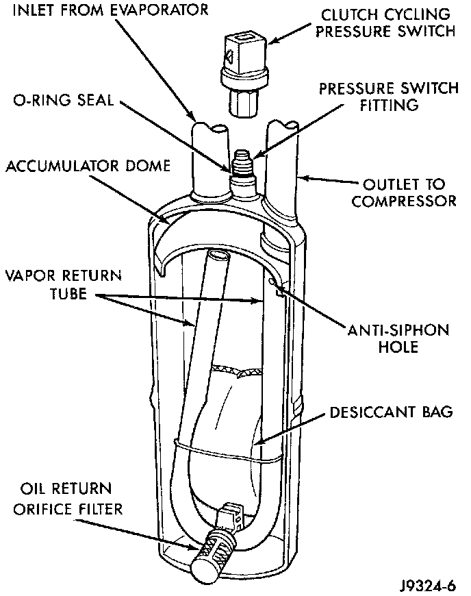
Fig 2 Accumulator -- Typical:
ACCUMULATOR
The accumulator is mounted in the engine compartment between the evaporator coil outlet tube and the compressor inlet. Refrigerant enters the accumulator canister as a low pressure vapor through the inlet tube.
Any liquid, oil-laden refrigerant falls to the bottom of the canister, which acts as a separator. A desiccant bag is. mounted inside the accumulator canister to absorb any moisture which may have entered and become trapped in the refrigerant system.
BLOWER MOTOR
The blower motor and blower wheel are located in the passenger side end of the heater-A/C housing, below the glove box. The blower motor controls the velocity of air flowing through the heater-A/C housing by spinning a squirrel cage-type blower wheel within the housing at the selected speed. The blower motor and wheel can be removed from the engine compartment side of the housing without heater-A/C housing removal.
The blower motor will only operate when the ignition switch is in the On position, and the heater-A/C mode control switch knob is in any position. except Off. The blower motor receives ground feed at all times.
The blower motor battery feed circuit is protected by a fuse in the fuseblock module.
Blower motor speed is controlled by regulating the battery feed through the blower motor switch, blower motor resistor and high speed blower motor relay.
The blower motor and blower motor wheel cannot be repaired and, if faulty, they must be replaced. The blower motor and blower wheel are serviced only as a unit.
BLOWER MOTOR RESISTOR
The blower motor resistor is mounted to the bottom of the heater-A/C housing on the passenger side of the vehicle under the instrument panel. On models with the optional air conditioning, it can be accessed by removing the recirculation air door actuator kick cover.
The resistor has multiple resistor wires, each of which reduce the current flow to the blower motor to change the blower motor speed.
The blower motor switch directs current through the correct resistor wire to obtain the selected speed.
The blower motor resistor cannot be repaired and, if faulty, it must be replaced.
BLOWER MOTOR SWITCH
The heater or heater-A/C blower motor is controlled by a four position rotary-type blower motor switch, mounted in the heater-A/C control panel. The switch allows the selection of one of four blower motor speeds, but can only be turned off by selecting the Off position with the heater-A/C mode control switch knob.
The blower motor switch receives ignition-switched battery feed through the mode control switch from a fuse in the fuseblock module. The switch directs the current to the blower motor resistor, or to the high speed blower motor relay, as required to achieve the selected blower motor speed.
The blower motor switch cannot be repaired and, if faulty, it must be replaced.
COMPRESSOR
The air conditioning system uses a Sanden SD7H15 fixed displacement compressor on all models. A label identifying the use of R-134a refrigerant is located on the compressor. The purpose of the compressor is to compress the low-pressure refrigerant vapor from the evaporator into a high-pressure, high temperature vapor. The compressor is serviced only as an assembly.
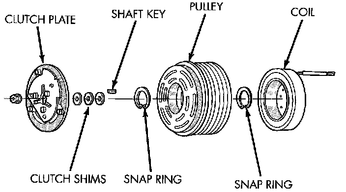
Fig 3 Compressor Clutch:
COMPRESSOR CLUTCH
The compressor clutch assembly consists of a stationary electromagnetic coil, a hub hearing and pulley assembly, and a clutch plate. The electromagnetic coil and pulley are retained on the compressor with snap rings. The clutch plate is mounted on the compressor shaft and secured with a nut.
These components provide the means to engage and disengage the compressor from the engine serpentine accessory drive belt. When the clutch coil is energized, it magnetically draws the clutch into contact with the pulley and drives the compressor shaft. When the coil is not energized, the pulley freewheels on the clutch hub bearing, which is part of the pulley The compressor clutch and coil are the only serviced parts on the compressor.
The compressor clutch is controlled by several components: the heater-A/C mode control switch, the low pressure cycling clutch switch, the high pressure cutoff switch, the compressor clutch relay, and the Powertrain Control Module (PCM). The PCM may delay compressor clutch engagement for up to 30 seconds.
COMPRESSOR CLUTCH RELAY
The compressor clutch relay is a International Standards Organization (ISO) micro-relay. The terminal designations and functions are the same as a conventional ISO relay. However, the micro-relay terminal orientation (footprint) is different, current capacity is lower, and the relay case dimensions are smaller than those of the conventional ISO relay.
The compressor clutch relay is a electromechanical device that switches battery current to the compressor clutch coil when the Powertrain Control Module (PCM) grounds the coil side of the relay. The PCM responds to inputs from the heater-A/C mode control switch, the low pressure cycling clutch switch, and the high pressure cut-off switch.
The compressor clutch relay is located in the Power Distribution Center (PDC) in the engine compartment. Refer to the PDC label for relay identification and location.
The compressor clutch relay cannot be repaired and, if faulty or damaged, it must be replaced.
CONDENSER
The condenser is located in front of the engine cooling radiator. It is a heat exchanger that allows the high-pressure refrigerant gas to give up its heat to the air passing over the condenser fins. This causes the refrigerant gas to condense into a high-pressure liquid refrigerant.
The condenser cannot be repaired and, if faulty or damaged, it must be replaced.
EVAPORATOR COIL
The evaporator coil is located in the heater-A/C housing, under the instrument panel. Refrigerant enters the evaporator as a low-temperature, low- pressure liquid. As air passes over the fins of the evaporator, the humidity in the air condenses on the fins, and the heat from the air is absorbed by the refrigerant. Heat absorption causes the refrigerant to become a low-pressure gas before it leaves the evaporator.
The evaporator coil cannot be repaired and, if faulty or damaged, it must be replaced.
FIXED ORIFICE TUBE
The fixed orifice tube is installed in the liquid line between the outlet tube of the condenser and the inlet tube of the evaporator. The fixed orifice tube is located in the end of the liquid line that connects to the condenser outlet tube.
The inlet and outlet ends of the tube have screen to filter the refrigerant. O-rings on the tube body prevent the refrigerant from bypassing the fixed orifice. The fixed orifice tube is used to meter the flow of liquid refrigerant into the evaporator coil.
The fixed orifice tube cannot be repaired and, if faulty or plugged, the liquid line or liquid line jumper containing the fixed orifice tube must be replaced.
HEATER CORE
The heater core is located in the heater-A/C housing, under the instrument panel. It is a heat exchanger made of rows of tubes and fins. Engine coolant is circulated through heater hoses to the heater core at all times. As the coolant flows through the heater core, heat removed from the engine is transferred to the heater core fins and tubes.
Air directed through the heater core picks up the heat from the heater core fins. The blend air door allows control of the heater output air temperature by controlling how much of the air flowing through the heater-A/C housing is directed through the heater core. The blower motor speed controls the amount of air flowing through the heater-A/C housing.
The heater core cannot be repaired and, if faulty or damaged, it must be replaced.
HIGH PRESSURE CUT-OFF SWITCH
The high pressure cut-off switch is located on the discharge line near the compressor. This switch is connected in series with the low pressure cycling clutch switch between ground and the Powertrain Control Module (PCM). The switch contacts open and close causing the PCM to turn the compressor clutch on and off. This prevents compressor operation when the discharge line pressure approaches high levels.
The high pressure cut-off switch contacts are open when the discharge line pressure rises above 3100 to 3375 kPa (450 to 490 psi). The switch contacts will close when the discharge line pressure drops to 1860 to 2275 kPa (270 to 330 psi).
The high pressure cut-off switch is a factory-calibrated unit. The switch cannot be adjusted or repaired and, if faulty or damaged, it must be replaced.
HIGH PRESSURE RELIEF VALVE
The high pressure relief valve is located on the compressor. The valve is used to prevent excessive refrigerant system pressure. The valve vents the system when a pressure of 3445 to 4135 kPa (500 to 600 psi I, and above, is reached. This prevents damage to the compressor and other system components due to condenser air flow being restricted or an overcharge of refrigerant. The valve closes with a minimum pressure of 2756 kPa (400 psi).
The high pressure relief valve vents only enough refrigerant to reduce system pressure, and then re-seats itself. The majority of the refrigerant is conserved in the system. If the valve vents refrigerant, it does not mean the valve is faulty. The valve is part of the compressor assembly and must not be removed or otherwise disturbed.
HIGH SPEED BLOWER MOTOR RELAY
The blower motor relay is a International Standards Organization (ISO)-type relay. The relay is a electromechanical device that switches battery current from a fuse in the Power Distribution Center (PDC) to the blower motor, bypassing the remainder of the blower motor feed circuit. The relay is energized when the relay coil is provided a voltage signal by the blower motor switch.
The High Speed Blower Motor Relay is located near the passenger side end of the heater-A/C wire harness connector.
The blower motor relay cannot be repaired and, if faulty or damaged, it must be replaced.
LOW PRESSURE CYCLING CLUTCH SWITCH
The low pressure cycling clutch switch is mounted on top of the accumulator. The switch is connected in series with the high pressure cut-off switch, between ground and the Powertrain Control Module (PCM). The switch contacts open and close causing the PCM to turn the compressor clutch on and off. This regulates the system pressure and controls evaporator temperature. Controlling evaporator temperature prevents condensate water on the evaporator fins from freezing and obstructing air conditioning system air flow.
The low pressure cycling clutch switch contacts are open when the suction pressure is approximately 141 kPa (20.5 psi) or lower. The switch contacts will close when the suction pressure rises to approximately 234 to 262 kPa (34 to 38 psi) or above. Lower ambient temperatures, below approximately -10C (30'F) during cold weather will also open the switch contacts. This is due to the pressure/temperature relationship of the refrigerant in the system.
The low pressure cycling clutch switch is a factory- calibrated unit. It cannot be adjusted or repaired and, if faulty or damaged, it must be replaced.
REFRIGERANT
The R-134a refrigerant used in this air conditioning system is a non-toxic, non-flammable, clear, and colorless liquefied gas. R-134a refrigerant is not compatible with R-12 refrigerant in an air conditioning system.
Even a small amount of R-12 added to a R-134a refrigerant system, will cause compressor failure refrigerant oil sludge, or poor air conditioning system performance. The refrigerant system service ports have been designed to ensure that the system is not accidentally filled with the wrong refrigerant (R-12).
REFRIGERANT LINE
The refrigerant lines are used to carry the refrigerant between the various air conditioning system components. A barrier hose design is used for the air conditioning system on this vehicle. The ends of the refrigerant hoses are made from lightweight aluminium, and use braze-less fittings.
Kinks or sharp bends in the refrigerant plumbing will reduce the capacity of the entire system. High pressures are produced in the system when it is operating. Extreme care must be exercised to make sure that all refrigerant system connections are pressure tight.
A good rule for the flexible hose refrigerant lines ii to keep the radius of all bends at least ten times the diameter of the hose. Sharp bends will reduce the flow of refrigerant. The flexible hose lines should be routed so they are at least 80 mm (3 inches) from the exhaust manifold. It is a good practice to inspect all flexible refrigerant system hose lines at least once a year to make sure they are in good condition and properly routed.
The refrigerant lines and hoses cannot be repaired and, if faulty or damaged, they must be replaced.
REFRIGERANT LINE COUPLER
Spring-locking refrigerant line couplers are used to connect refrigerant lines and other components to the refrigerant system. The coupling is held together by a garter spring inside a circular cage.
When the coupling halves are connected, the flared end of the female fitting slips behind the garter spring inside the cage of the male fitting. The garter spring and cage prevent the flared end of the female fitting from pulling out of the cage. Secondary clips are installed over the coupling at the factory for added blowoff protection.
O-rings are used to seal the coupling. These O-rings are compatible with R-134a refrigerant and must be replaced with O-rings made of the same material.
REFRIGERANT OIL
The oil used in the SD7H15 compressor is a polyalkylene glycol, synthetic (SP-2O PAG), wax-free refrigerant oil. Use only refrigerant oil of the same type to service the system.
Refrigerant oil will absorb any moisture it comes in contact with, even moisture in the air. The oil container should be kept tightly capped until it is ready to be used. Then, cap the oil immediately after using, to prevent contamination.
VACUUM CHECK VALVE
A one-way vacuum check valve is installed in the accessory vacuum supply line near the vacuum tap on the engine intake manifold in the engine compartment This check valve helps to maintain the system vacuum needed to retain the selected heater-A/C mode settings by preventing the engine from bleeding down system vacuum through the intake manifold during extended heavy engine load (low engine vacuum) operation.
The vacuum check valve cannot be repaired and, if faulty or damaged, it must be replaced.
VACUUM RESERVOIR
The vacuum reservoir is mounted to the front bumper bar behind the passenger side bumper end cap. Vacuum stored in the reservoir is used to operate the vacuum-controlled vehicle accessories during periods of low engine vacuum, such as when the vehicle is climbing a steep grade or under other high engine load operating conditions.
The vacuum reservoir cannot be repaired and, if faulty or damaged, it must be replaced.
INTRODUCTION
The vehicle may be equipped with a heater only or with air conditioning and heater. The wiring diagrams contain schematics for Heater Only and A/C-Heater. The circuit descriptions address both conditions. When referring to the wiring diagrams, ensure you use the correct ones.
CIRCUIT OPERATION
When the A/C-heater control switch is moved to an A/C position or the defrost position, it connects circuit C90 to ground on circuit Z1. Circuit C90 connects to cavity C23 of the Powertrain Control Module (PCM) and splices to the A/C high pressure switch. When circuit C90 connects to ground circuit Z1 it provides the A/C select signal to the PCM.
When the A/C high pressure switch closes, it connects circuit C90 to circuit C21. Circuit C21 connects to the A/C cycling switch. If the A/C cycling switch is closed, it connects circuit C21 to circuit C22. Circuit C22 connects to cavity C22 of the PCM. The PCM senses the A/C request signal on circuit C22 when the A/C-heater control switch is in defrost or an A/C position and the high pressure and cycling switches are closed.
After sensing the A/C request signal, the PCM supplies ground for the coil side of A/C compressor clutch relay on circuit C13. Circuit C13 originates at cavity C1 of the PCM. Circuit F12 from fuse 11 in the fuse block powers the coil side of the A/C compressor clutch relay.
When the PCM grounds the A/C compressor clutch relay, the contacts close and connect circuit A17 from fuse 19 in the PDC to circuit C3. Circuit C3 supplies power to the case grounded A/C compressor clutch.
The A/C compressor clutch has a built-in diode. The diode controls the induced voltage that results from the magnetic field collapsing when the clutch disengages. The diode provides a current path to protect other components and systems.