Battery: Description and Operation
OVERVIEWThe battery, starting, and charging systems operate with one another, and must be tested as a complete system. In order for the vehicle to start and charge properly, all of the components involved in these systems must perform within specifications.
When attempting to diagnose any of systems, it is important that you keep their interdependency in mind.
The diagnostic procedures used include the most basic conventional diagnostic methods to the more sophisticated On-Board Diagnostics (OBD) built into the Powertrain Control Module (PCM) Use of a induction milliampere ammeter, volt/ ohmmeter, battery charger, carbon pile rheostat (load tester), and 12 Volt test lamp may be required.
All OBD-sensed systems are monitored by the PCM. Each monitored circuit is assigned a Diagnostic Trouble Code (DTC). The PCM will store a DTC in electronic memory for any failure it detects. Refer to Powertrain Management/Computer and Control System for more information.
INTRODUCTION
This covers battery diagnostic and service procedures only. For battery maintenance procedures, While battery charging can be considered a maintenance procedure, battery charging information is located. This was done because the battery must be fully-charged before any diagnosis can be performed.
Low Maintenance Battery-Typical:
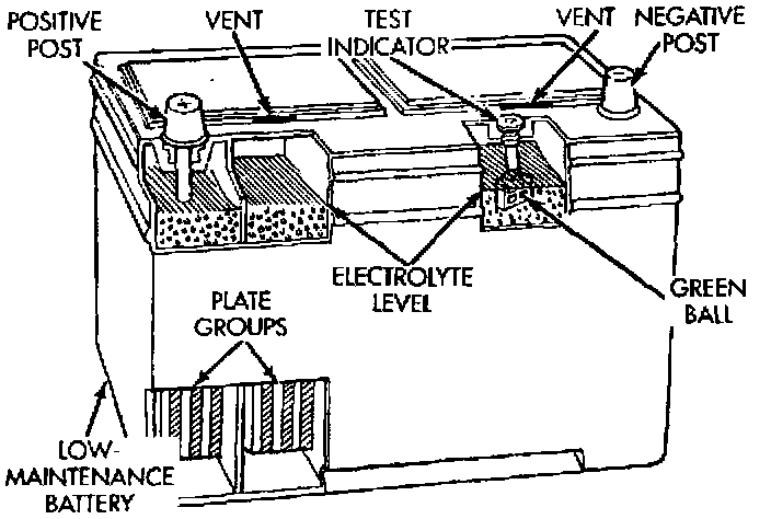
The factory-installed low-maintenance battery has removable battery cell caps. Water can be added to this battery. The battery is not sealed and has vent holes in the cell caps. The chemical composition within the low-maintenance battery reduces battery gassing and water loss at normal charge and discharge rates.
Rapid loss of electrolyte can be caused by an overcharging condition. Be certain to diagnose the charging system before returning the vehicle to service. Refer to Starting and Charging/Charging System for more information.
The factory-installed battery also has a built-in test indicator (hydrometer). The color visible in the sight glass of the indicator will reveal the battery condition. See Built-In Test Indicator for more information.
It is important that the battery, starting, and charging systems be thoroughly tested and inspected any time a battery needs to be charged or replaced. The cause of abnormal discharge, overcharging, or early battery failure must be diagnosed and corrected before a battery is replaced or returned to service.
NOTE: This covers both Left-Hand Drive (LHD) and Right-Hand Drive (RHD) versions of this model. Whenever required and feasible, the RHD versions of affected vehicle components have been constructed as mirror-image of the LHD versions. While most of the illustrations used represent only the LHD version, the diagnostic and service procedures outlined can generally be applied to either version. Exceptions to this rule have been clearly identified as LHD or RHD, if a special illustration or procedure is required.
SYSTEM OPERATION
The storage battery is a device used to store electrical energy potential in a chemical form. When an electrical load is applied to the battery terminals, an electrochemical reaction occurs within the battery. This reaction causes the battery to discharge electrical current.
The battery is made up of six individual cells that are connected in series. Each cell contains positively charged plate groups made of lead oxide, and negatively charged plate groups made of sponge lead. These dissimilar metal plates are submerged in a sulfuric acid and water solution called an electrolyte.
As the battery discharges, a gradual chemical change takes place within each cell. The sulfuric acid in the electrolyte combines with the plate materials, causing both plates to slowly change to lead sulfate. At the same time, oxygen from the positive plate material combines with hydrogen from the sulfuric acid, causing the electrolyte to become mainly water.
The chemical changes within the battery are caused by the movement of excess, or free, electrons between the positive and negative plate groups. This movement of electrons produces a flow of electrical current through the load device attached to the battery terminals.
As the plate materials become more similar chemically, and the electrolyte becomes less acid, the voltage potential of each cell is reduced. However, by charging the battery with a voltage higher than that of the battery, the battery discharging process is reversed.
Charging the battery gradually changes the sulfated lead plates hack into sponge lead and lead oxide, and the water back into sulfuric acid. This action restores the difference in the electron charges deposited on the plates, and the voltage potential of the battery cells.
For a battery to remain useful, it must be able to produce high-amperage current over an extended period. A battery must also be able to accept a charge, so that its voltage potential may be restored.
In addition to producing and storing electrical energy, the battery serves as a capacitor, or voltage stabilizer, for a vehicle's electrical system. It absorbs most abnormal or transient voltages caused by the switching of any of the vehicle's electrical components.
The battery is vented to release excess hydrogen gas that is created when the battery is being charged or discharged. However, even with these vents, the hydrogen gas can collect in or around the battery If hydrogen gas is exposed to flame or sparks, it may ignite.
If the electrolyte level is low, the battery may arc internally and explode. If the battery is equipped with removable cell caps, add distilled water whenever the electrolyte level is below the top of the plates. If the battery cell caps cannot be removed, the battery must be replaced if the electrolyte level becomes low.
Battery Size And Ratings
The outside dimensions and terminal placement of the battery conform to standards established by the Battery Council International (BCI). Each battery is assigned a BCI Group Size number to help identify a correctly-sized replacement.
In addition, there are two commonly accepted methods for rating and comparing battery performance. These ratings are called Cold Cranking Amperage (CCA) and Reserve Capacity (RC). A third rating method used in many export markets is called Ampere-Hours (AH). Each rating is described in more detail below.
The Group Size number, CCA rating, RC rating and, where applicable, the AH rating can be found on the original equipment battery label. Be certain that a replacement battery has the correct Group Size number, as well as CCA, and RC or AH ratings that equal or exceed the original equipment specification for the vehicle being serviced. See the Battery Classifications and Ratings chart in Specification for more information.
Cold Cranking Amperage
The Cold Cranking Amperage (CCA) rating specifies how much current (in amperes) the battery can deliver for 30 Seconds at -18°C (0°F). Terminal voltage must not fall below 7.2 Volts during or after the 30 Second discharge. The CCA required is generally higher as engine displacement increases, depending also upon the starter current draw requirements.
Reserve Capacity
The Reserve Capacity (RC) rating specifies the time (in minutes) it takes for battery terminal voltage to fall below 10.2 Volts, at a discharge rate of 25 amps. RC is determined with the battery fully charged at 26.7°C (80°F). This rating estimates how long the battery might last after a charging system failure, under minimum electrical load.
Ampere-hours
The Ampere-Hours rating specifies the current (in amperes) that a battery can deliver steadily for 20 Hours, with the voltage in none of the battery cells falling below 1.75 Volts. This rating is also sometimes referred to as the 20 Hour discharge rating.
Battery Mounting
The battery is mounted to a stamped steel tray located in the passenger side rear corner of the engine compartment. A J-bolt is inserted through holes on the front and rear edges of the tray A hold-down strap fits across the top of the battery case and thermoguard. The J-bolts pass through the hold- down strap on each side of the battery, and a nut secures the J-bolts to the hold-down strap.
The battery tray is fastened with four screws to a support bracket mounted between the front fender inner wheelhouse and the dash panel, rearward of the passenger side front wheel.
A hole in the bottom of the battery tray is fitted with a battery temperature sensor on some models. Models without the battery temperature sensor have a plug fitted to this hole. Refer to Starting and Charging/Battery for more information on the battery temperature sensor.